00192791-02.pdf - 第55页
User Manual 2 Ceramic Substrate Centering Unit Software Version S R.502.xx 01/01 Issue 2.6 Utilizing Oblique lllumination to Recognize the Position of a Fiducial 55 5HFRPPHQGDWLRQV IRU)LGXFLDOVRQ&HUD PLF6X…
2 Ceramic Substrate Centering Unit User Manual SIPLACE HS-50
2.6 Utilizing Oblique lllumination to Recognize the Position of a Fiducial Software Version SR.502.xx 01/01 Issue
54
8WLOL]LQJ2EOLTXHOOOXPLQDWLRQWR5HFRJQL]HWKH
3RVLWLRQRID)LGXFLDO
*HQHUDO,QIRUPDWLRQ
The particular features of the ceramic substrate must be taken into consideration when trying to
recognize the position of fiducials on ceramic substrates. The contrast depends very highly on
the properties of the surface the fiducials are on, just how unobstructed area around the fiducial
is, and the type of illumination selected.
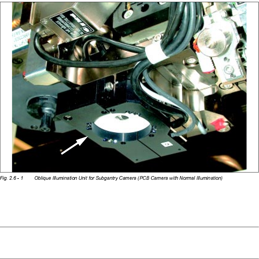
The optional oblique illumination unit is located on the front of the subgantry PCB camera.
As an alternative to the existing illumination of the subgantry PCB camera with normal illumina-
tion, you can switch ON this oblique illumination (see table in Section 2.2 and Section 2.6).
NOTE:
The oblique illumination can only be used on the subgantry PCB camera (with normal illumina-
tion).
User Manual 2 Ceramic Substrate Centering Unit
Software Version SR.502.xx 01/01 Issue 2.6 Utilizing Oblique lllumination to Recognize the Position of a Fiducial
55
5HFRPPHQGDWLRQV IRU)LGXFLDOVRQ&HUD PLF6XEVW UDWHV
With ceramic substrates there is generally very little contrast between carrier material and the
coating on the PCB. For this reason, specific criteria regarding the shape and layout of the fidu-
cial must be taken into account when selecting the fiducials. See the following recommendations
for the shape and layout of fiducials.
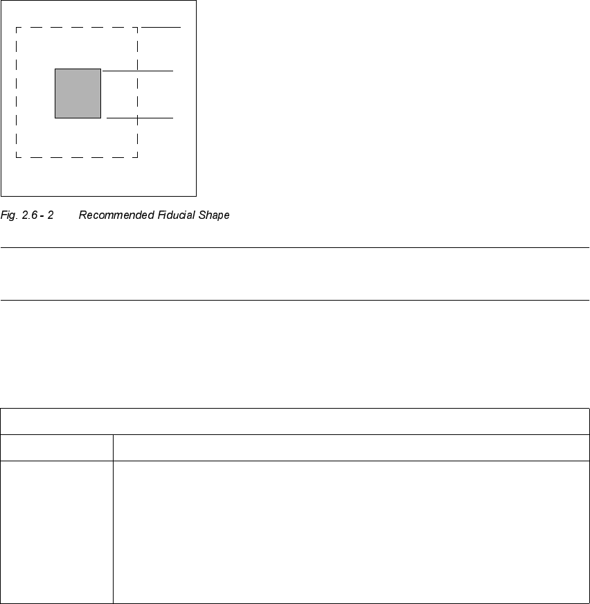
)LGXFLDO6KDSH
We suggest a rectangular or square with an edge length of > 1 mm and a clearance of > 0.1 mm.
NOTE
Single crosses are also suitable, however they require more space.
/D\RXWRI)LGXFLDOV
1.0 mm
1.0 mm
0DWHULDOHJ5HVLVWRU3DVWH
Fiducial layout Black resistor paste as a background and conductor paste printed on it as a fiducial.
Recommendation Background > 1.0 mm bigger than the fiducial on all sides.
Always use printed conductor layer as a reference -> Accuracy
Generally, sufficient contrast is created with the PCB camera multicolor, except in the
case of AgPt.
2 Ceramic Substrate Centering Unit User Manual SIPLACE HS-50
2.7 Screen "Conveyor Functions" Software Version SR.502.xx 01/01 Issue
56
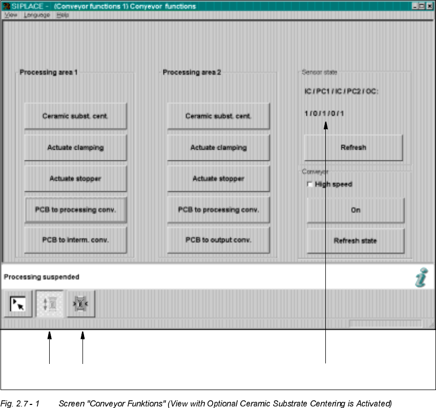
6FUHHQ&RQY H\RU)XQFWLRQV
The "Conveyor functions" (also named "Conveyor functions") are used for checking and adjusting
the functional modules of the PCB conveyor system / of the mechanical ceramic substrate cen-
tering unit.
.H\
(1) Functions for PCB conveyor
(2) Functions to adjust the width of the PCB conveyor
(3) Functions to display the state of the ultrasonic senors
12
3