Transport Rails Module.pdf - 第10页
TRANSPORT RAILS MODULE ADJUSTMENTS AND SETTINGS 16.10 Technical Reference Manu al Chapter Issue 4 Jan 10 27. Confirm which type of rails are fitted to the machine and select the appropri- ate rail setting jig. 28. Place …
TRANSPORT RAILS MODULE
ADJUSTMENTS AND SETTINGS
Chapter Issue 4 Jan 10 Technical Reference Manual 16.9
Front Rail Parallelism
WARNING
BOARD CLAMPS. EXTREME CARE MUST BE EXERCISED WHEN WORKING IN
THE TOOLING AREA OF THE MACHINE TO AVOID INJURY. THE FOILS ON THE
FRONT AND REAR BOARD CLAMPS ARE VERY SHARP.
NOTE
The Front Rail Parallelism is factory set and shouldn’t normally need to be
adjusted.
1. Select Open Cover Commands.
2. Select Carriage To Rear.
3. Select Unload Screen.
4. Open the front printhead cover.
5. Remove the screen from the machine.
6. Close the front printhead cover.
7. Press the System button.
8. Select Back.
9. Select Maintenance.
10. Select Diagnostics.
11. Use Next or Previous to highlight Rail System.
12. Select Select Module.
13. Ensure that Home Rail Width is highlighted.
14. Select Run Diagnost.
15. Select Exit.
16. Use Next or Previous to highlight Rising Table.
17. Select Select Module.
18. Use Next or Previous to highlight Raise Table to Vision Height.
19. Select Run Diagnost.
20. Select Exit.
21. Use Next or Previous to highlight Rail System.
22. Select Select Module. The board clamps are released.
23. Open the front printhead cover.
24. Remove any tooling from the manual tooling plate.
25. Remove the board clamp from the front transport rail, Board Clamp
Replacement - Replacement Procedures section of this chapter refers.
26. There are two versions of the rail setting jig (DEK Part No. 191156) and they
are labelled:
• Standard Rails (round belts)
• Heavy Board Rails (flat belts)
TRANSPORT RAILS MODULE
ADJUSTMENTS AND SETTINGS
16.10 Technical Reference Manual Chapter Issue 4 Jan 10
27. Confirm which type of rails are fitted to the machine and select the appropri-
ate rail setting jig.
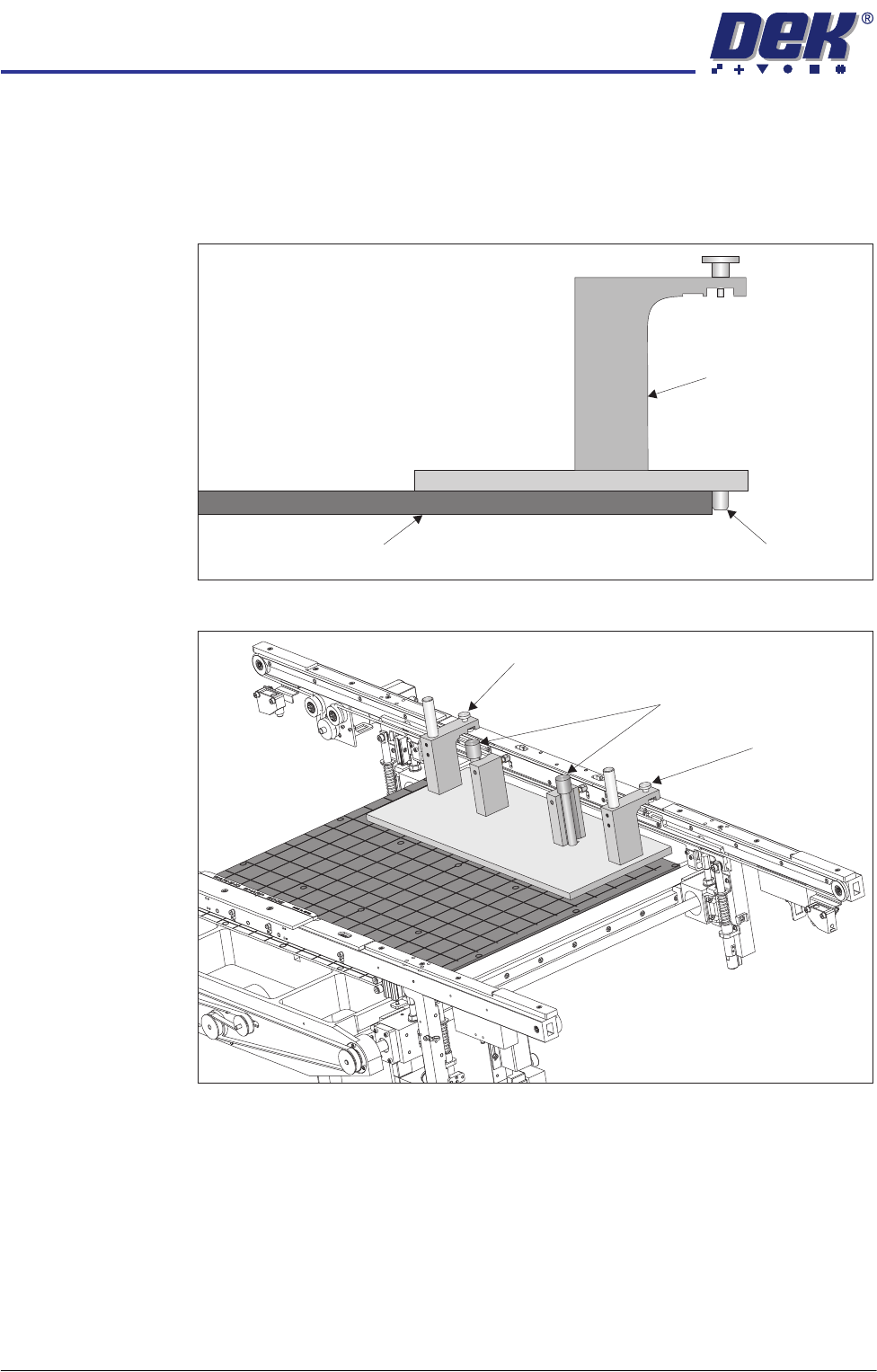
28. Place the jig on the manual tooling plate ensuring that the location pins on
the underside of the jig abut the front face of the manual tooling plate. Check
there is no gap using a 0.05mm feeler gauge.
29. Secure the jig to the front rail using the two jig to rail thumbscrews.
30. Secure the jig to the rising table using the two jig to table thumbscrews.
31. Check that the location pins are up against the front edge of the manual
tooling plate using a 0.05mm feeler gauge, as in Step 28.
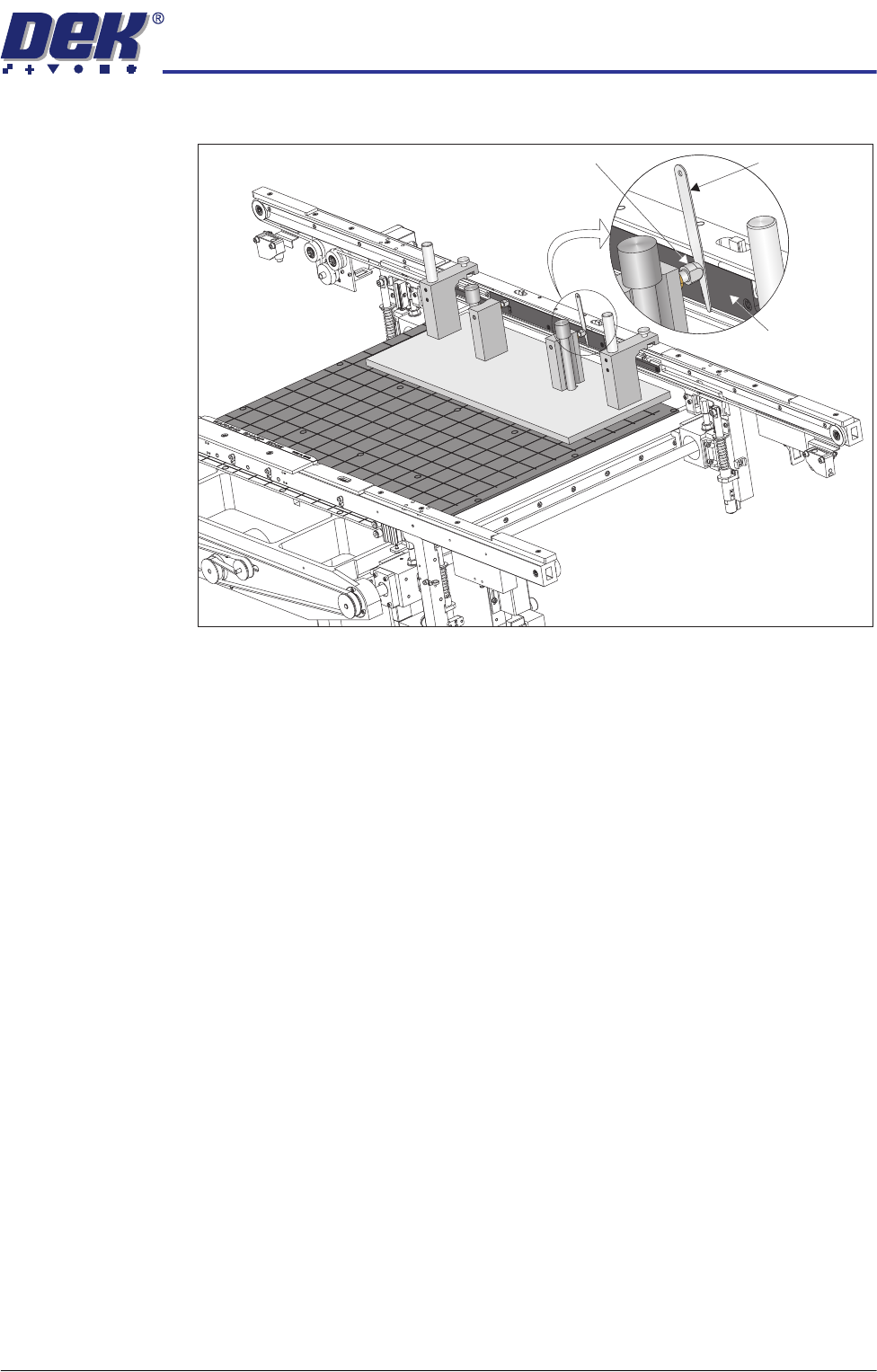
32. Using feeler gauges check that the gap between both alignment pads and
View on Left Hand Side
Manual Tooling Plate Location Pin
Rail Setting Jig
View on Rear of Transport Rails
Jig to Table Thumbscrews
Jig to Rail Thumbscrew
Jig to Rail Thumbscrew
TRANSPORT RAILS MODULE
ADJUSTMENTS AND SETTINGS
Chapter Issue 4 Jan 10 Technical Reference Manual 16.11
the belt support plate of the front rail is 0.25mm ±0.05mm.
33. If adjustment is not necessary continue with Step 46.
Feeler Gauge
Alignment
Pad
Belt Support
Plate
View on Rear of Transport Rails