Transport Rails Module.pdf - 第12页
TRANSPORT RAILS MODULE ADJUSTMENTS AND SETTINGS 16.12 Technical Reference Manu al Chapter Issue 4 Jan 10 34. Using a 3mm Allen key slacken the four securing bolts att aching the right hand transport leg to the carr iage …
TRANSPORT RAILS MODULE
ADJUSTMENTS AND SETTINGS
Chapter Issue 4 Jan 10 Technical Reference Manual 16.11
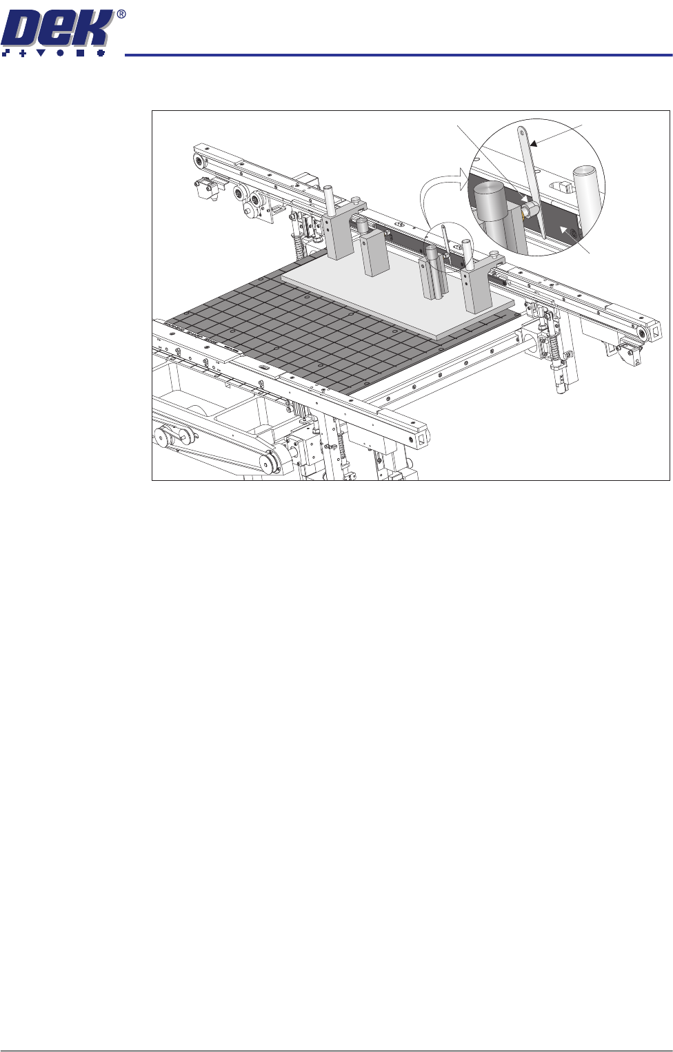
the belt support plate of the front rail is 0.25mm ±0.05mm.
33. If adjustment is not necessary continue with Step 46.
Feeler Gauge
Alignment
Pad
Belt Support
Plate
View on Rear of Transport Rails
TRANSPORT RAILS MODULE
ADJUSTMENTS AND SETTINGS
16.12 Technical Reference Manual Chapter Issue 4 Jan 10
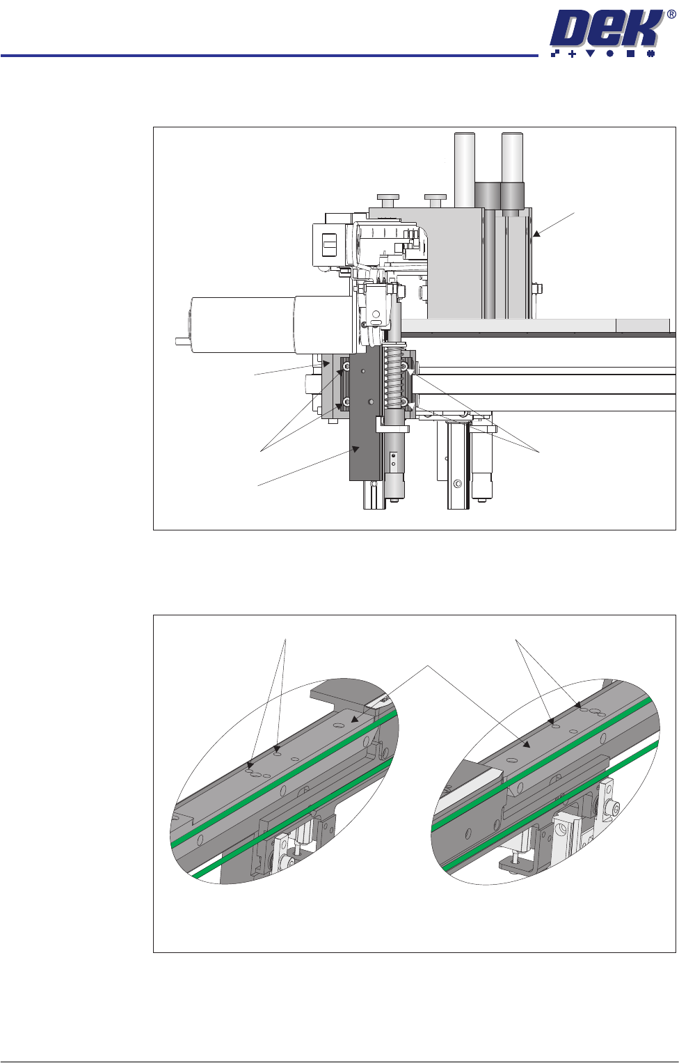
34. Using a 3mm Allen key slacken the four securing bolts attaching the right
hand transport leg to the carriage nut.
35. Repeat Step 34 on the left hand transport leg.
36. Using a 4mm Allen key, through the access holes in the board edge guide,
slacken the four rail securing bolts (two each side).
37. Loosen the two jig to rail thumbscrews on the rail setting jig.
38. Adjust the front rail position to achieve the settings in Step 32.
39. Tighten the two jig to rail thumbscrews on the rail setting jig.
Rail Setting Jig
Securing Bolts
Securing Bolts
Transport Leg
View on Right Hand Side of Front Transport Rail
Carriage Nut
Access Holes
View on Inside of Front Rail
Left Hand End
View on Inside of Front Rail
Right Hand End
Access Holes
Board Edge Guides

TRANSPORT RAILS MODULE
ADJUSTMENTS AND SETTINGS
Chapter Issue 4 Jan 10 Technical Reference Manual 16.13
40. Recheck the parallelism as detailed in Step 32.
41. Tighten the bolts slackened in Steps 34 to 36.
42. Recheck the parallelism as detailed in Step 32.
43. When the adjustment is complete, remove the board edge guides from each
end of the rail.
44. Remove each bolt disturbed (one at a time), apply a suitable locking
compound and fully tighten.
45. Refit the board edge guide to each end of the rail.
46. Remove the rail setting jig from the rising table.
47. Fit the board clamp to the front rail.
48. Close the front printhead cover.
49. Press the System button.
50. Select Exit.
51. Select Exit.
52. Select Back.