Transport Rails Module.pdf - 第30页
TRANSPORT RAILS MODULE ADJUSTMENTS AND SETTINGS 16.30 Technical Reference Manu al Chapter Issue 4 Jan 10 65. Close the front printhead cover . 66. Press the System button. 67. Select Run Diagnost to release the board cla…
TRANSPORT RAILS MODULE
ADJUSTMENTS AND SETTINGS
Chapter Issue 4 Jan 10 Technical Reference Manual 16.29
52. Close the front printhead cover.
53. Press the System button.
54. Select Run Diagnost to energise the board clamps.
55. Open the front printhead cover.
NOTE
Do not touch the transport rails as this could affect the readings.
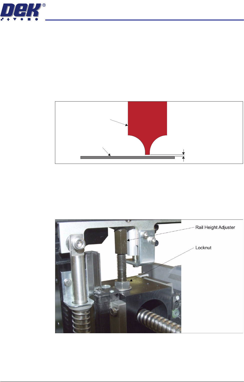
56. Using the feeler gauges, check that the gap between the height gauge and
the manual tooling plate is 0.013˝ ±0.001˝.
57. If adjustment is not required, go to Step 65.
58. Each transport rail is supported by two rail height adjusters. Decide which
rail height adjusters need to be adjusted to achieve the correct height for the
rails.
59. Remove the appropriate safety cover(s).
60. Using a 13mm spanner, release the rail height adjuster locknut.
61. Using a 10mm spanner, adjust the rail height adjuster to achieve the height
in Step 56.
62. Tighten the locknut.
63. Recheck the measurements.
64. Repeat Steps 60 to 63 if necessary.
0.013 ±0.001²²
Manual Tooling Plate
Height Gauge

TRANSPORT RAILS MODULE
ADJUSTMENTS AND SETTINGS
16.30 Technical Reference Manual Chapter Issue 4 Jan 10
65. Close the front printhead cover.
66. Press the System button.
67. Select Run Diagnost to release the board clamps.
68. Open the front printhead cover.
69. Remove the height gauges.
70. Remove the steel dowels (transport rails with round belts only).
71. Refit the transport belt (transport rails with round belts only).
72. Repeat Steps 38 to 71 for the rear transport rail.
73. Refit the safety cover(s).
74. Replace the tooling.
75. Refit the screen.
76. Close the front printhead cover.
77. Press the System button.
78. Select Exit.
79. Select Exit.
80. Select Back.
81. Select Load Screen.
82. Carry out the following calibrations:
• Vision Height, Camera System Module chapter refers
• Print Height, Rising Table Module chapter refers
TRANSPORT RAILS MODULE
REPLACEMENT PROCEDURES
Chapter Issue 4 Jan 10 Technical Reference Manual 16.31
REPLACEMENT PROCEDURES
Board Clamp Replacement
WARNING
BOARD CLAMPS. EXTREME CARE MUST BE EXERCISED WHEN WORKING IN
THE TOOLING AREA OF THE MACHINE TO AVOID INJURY. THE FOILS ON THE
FRONT AND REAR BOARD CLAMPS ARE VERY SHARP.
1. Select Open Cover Commands.
2. Select Carriage To Rear.
3. Select Unload Screen.
4. Open the front printhead cover.
5. Remove the screen from the machine.
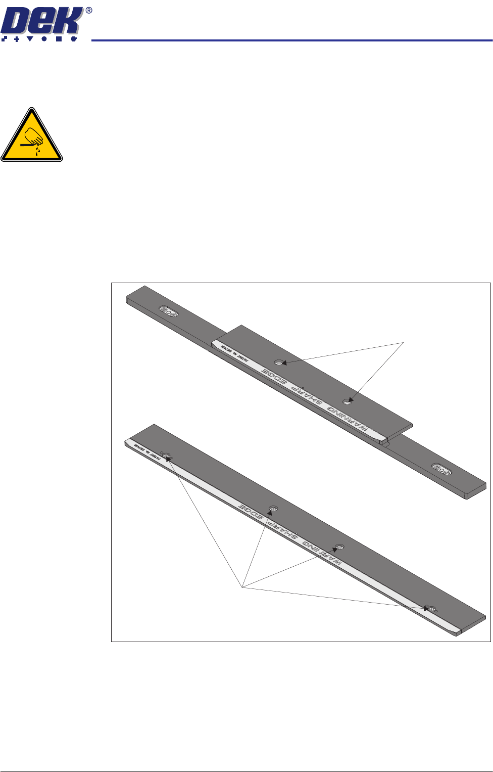
6. Remove the board clamp securing screws and remove the board clamp.
7. Place the new board clamp in position on the location plates.
8. Secure the board clamp in position with the screws removed in Step 6.
NOTE
The Board Clamp Setting procedure is not required after board clamp
replacement.
9. Refit the screen.
500mm Board Clamp Mechanism
Board Clamp Securing Screws
250mm Board Clamp Mechanism
Board Clamp Securing Screws