Transport Rails Module.pdf - 第17页
TRANSPORT RAILS MODULE ADJUSTMENTS AND SETTINGS Chapter Issue 4 Jan 10 Technical Reference Manu al 16.17 4. Remove the four board clamp securing screws and lift of f the board clamp. Retain the four screws. 5. Slacken th…
TRANSPORT RAILS MODULE
ADJUSTMENTS AND SETTINGS
16.16 Technical Reference Manual Chapter Issue 4 Jan 10
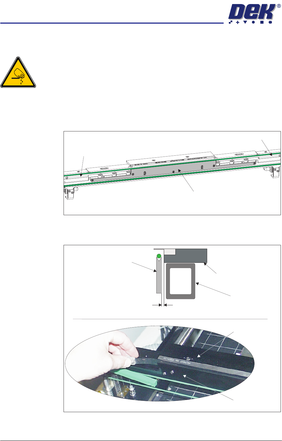
Board Clamp Setting
WARNING
BOARD CLAMPS. EXTREME CARE MUST BE EXERCISED WHEN WORKING IN
THE TOOLING AREA OF THE MACHINE TO AVOID INJURY. THE FOILS ON THE
FRONT AND REAR BOARD CLAMPS ARE VERY SHARP.
NOTE
Board clamps are used in the following procedure, the procedure is identical for
foil-less clamps and snuggers.
1. Remove the belt guide from either side of the belt support plate.
2. Using feeler gauges, check that the gap between the rear board clamp and
the belt support plate is 0.325mm ±0.025mm. Ensure that the rear board
clamp is parallel to the belt support plate.
3. If adjustment is necessary, go to Step 8 for 250mm board clamps and
continue with Step 4 for 500mm board clamps.
Belt Support Plate
Belt Guide
Belt Guide
View on Rear Rail
Cross Section of Rear Rail Assembly
View on Rear Board Clamp
Rear Board Clamp
Belt Support Plate
Belt Support Plate
Rear Board Clamp
Moving Rail
0.325mm 0.025mm±

TRANSPORT RAILS MODULE
ADJUSTMENTS AND SETTINGS
Chapter Issue 4 Jan 10 Technical Reference Manual 16.17
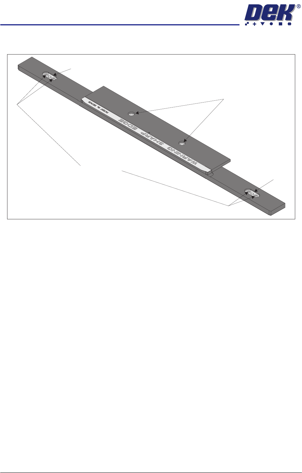
4. Remove the four board clamp securing screws and lift off the board clamp.
Retain the four screws.
5. Slacken the two location plate securing screws.
6. Place the board clamp in position, but do not fit the securing screws.
7. Go to Step 9.
500mm Board Clamp Mechanism
Board Clamp Securing Screws
Access Holes
View on Rear Rail (Board Clamp Removed)
Location Plate Securing Screws
TRANSPORT RAILS MODULE
ADJUSTMENTS AND SETTINGS
16.18 Technical Reference Manual Chapter Issue 4 Jan 10
8. Slacken the two location plate securing screws through the access slots.
9. Adjust the board clamp to achieve the setting of 0.325mm ±0.025mm
between the rear board clamp and the belt support plate.
10. When the correct setting has been achieved, either:
a. On 500mm board clamps, tighten the location plate securing screws
through the access holes in the board clamp, with a small bladed screw-
driver.
Or
b. On 250mm board clamps, tighten the location plate securing screws
through the access slots.
11. Recheck that the gap between the rear board clamp and the belt support
plate is 0.325mm ±0.025mm.
12. Repeat Steps 1 to 11 for the front board clamp.
13. Using a vernier gauge check that the board clamps are parallel, to within
0.1mm, at the left, centre and right of the board clamps.
14. If adjustment is necessary, slacken the location plate securing screws on the
rear rail and adjust. Tighten the location plate securing screws on comple-
tion.
15. If any adjustment is carried out, ensure the gap set in Step 9 is maintained.
16. For 250mm board clamps go to Step 20. For 500mm board clamps continue
with Step 17.
17. Lift off the rear rail board clamp and further tighten the location plate
securing screws, with a larger bladed screwdriver.
18. Place the rear rail board clamp in position and secure with the four securing
screws.
250mm Board Clamp Mechanism
Board Clamp Securing Screws
Location Plate Securing Screws
Access Slot
Access Slot