Transport Rails Module.pdf - 第36页
TRANSPORT RAILS MODULE REPLACEMENT PROCEDURES 16.36 Technical Reference Manu al Chapter Issue 4 Jan 10 13. Locate the magnetic plate on the righ t hand side of the machine cont aining the pneumatics for the snuggers. 14.…
TRANSPORT RAILS MODULE
REPLACEMENT PROCEDURES
Chapter Issue 4 Jan 10 Technical Reference Manual 16.35
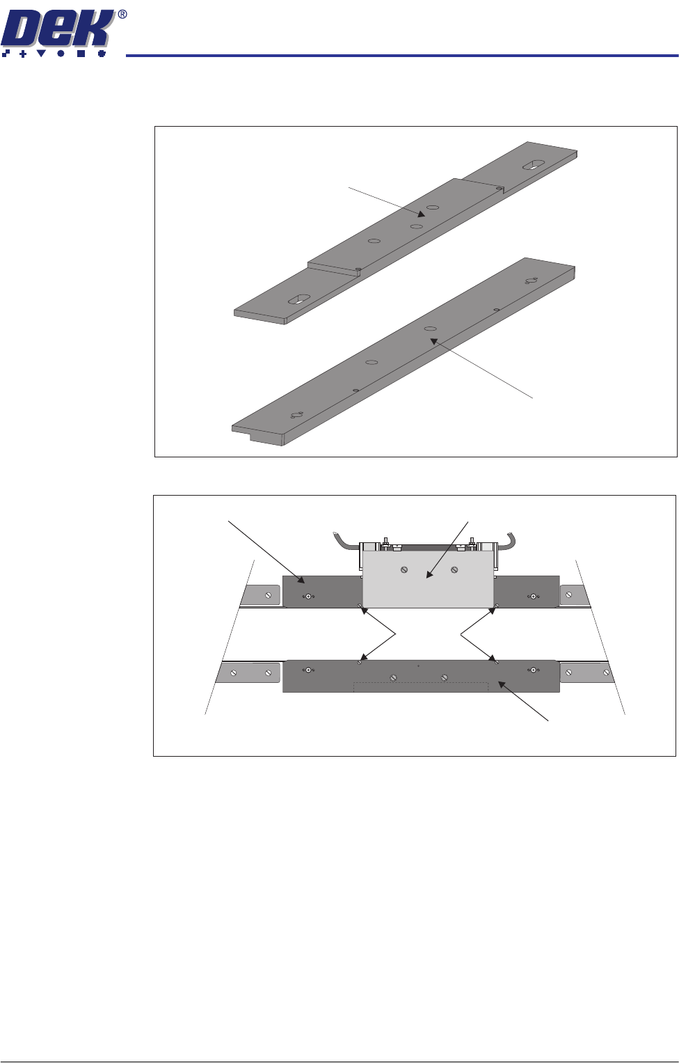
9. Fit the appropriate front snugger plate to the front rail and secure using the
M4 pan head screws.
10. Fit the rear snugger plate, don’t tighten the M4 pan head securing screws.
11. Close the front printhead cover.
12. Press the System button.
Front Snugger Plate -
Fixed Width Chase
Front Snugger Plate -
Adjustable Screen Mount (ASM)
Rear Snugger Plate
Front Snugger Plate
Downstops
Plan View of Rail System
Snugger Base Plate
TRANSPORT RAILS MODULE
REPLACEMENT PROCEDURES
16.36 Technical Reference Manual Chapter Issue 4 Jan 10
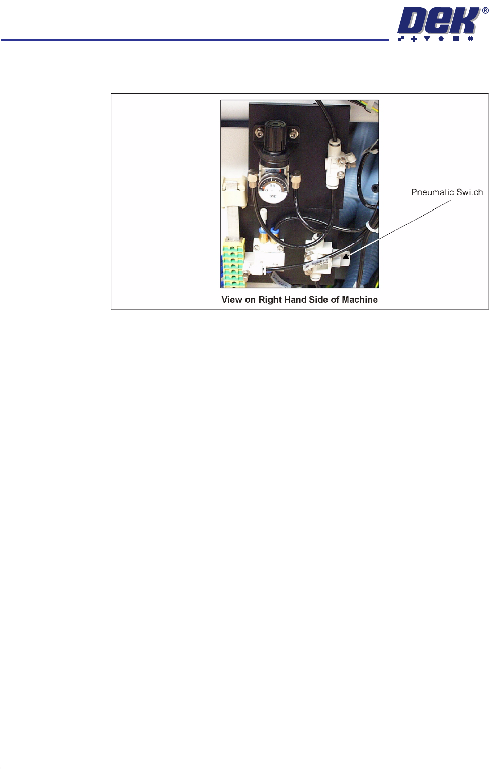
13. Locate the magnetic plate on the right hand side of the machine containing
the pneumatics for the snuggers.
14. Turn the pneumatic switch On.
15. Load the product file to be printed, the rear rail moves to set the board width.
NOTE
With Auto Rail Width set to Disabled the rear rail does not set the board
width, but it can still be moved in diagnostics.
16. Select Maintenance.
17. Select Machine Setup.
18. Select Basics.
19. Select Clamp Type.
20. Select Snuggers.
21. Select Accept.
22. Select Back.
23. Select Back.
24. Select Back.
25. Carry out Snugger Base Plate Height Adjustment in the Adjustments and
Settings section of this chapter.
NOTE
The Board Clamp Setting procedure is not required after board clamp/foil-less
clamp to snugger replacement.
TRANSPORT RAILS MODULE
REPLACEMENT PROCEDURES
Chapter Issue 4 Jan 10 Technical Reference Manual 16.37
Snuggers to Clamps
WARNING
BOARD CLAMPS. EXTREME CARE MUST BE EXERCISED WHEN WORKING IN
THE TOOLING AREA OF THE MACHINE TO AVOID INJURY. THE FOILS ON THE
FRONT AND REAR BOARD CLAMPS ARE VERY SHARP.
NOTE
This procedure is valid when converting to either board clamps or foil-less
clamps.
1. Select Open Cover Commands.
2. Select Carriage To Rear.
3. Select Unload Screen.
4. Open the front printhead cover.
5. Remove the screen from the machine.