Transport Rails Module.pdf - 第23页
TRANSPORT RAILS MODULE ADJUSTMENTS AND SETTINGS Chapter Issue 4 Jan 10 Technical Reference Manu al 16.23 2. Select Carriage T o Rear . 3. Select Unload Screen . 4. Open the front printhead cover . 5. Remove the screen fr…
TRANSPORT RAILS MODULE
ADJUSTMENTS AND SETTINGS
16.22 Technical Reference Manual Chapter Issue 4 Jan 10
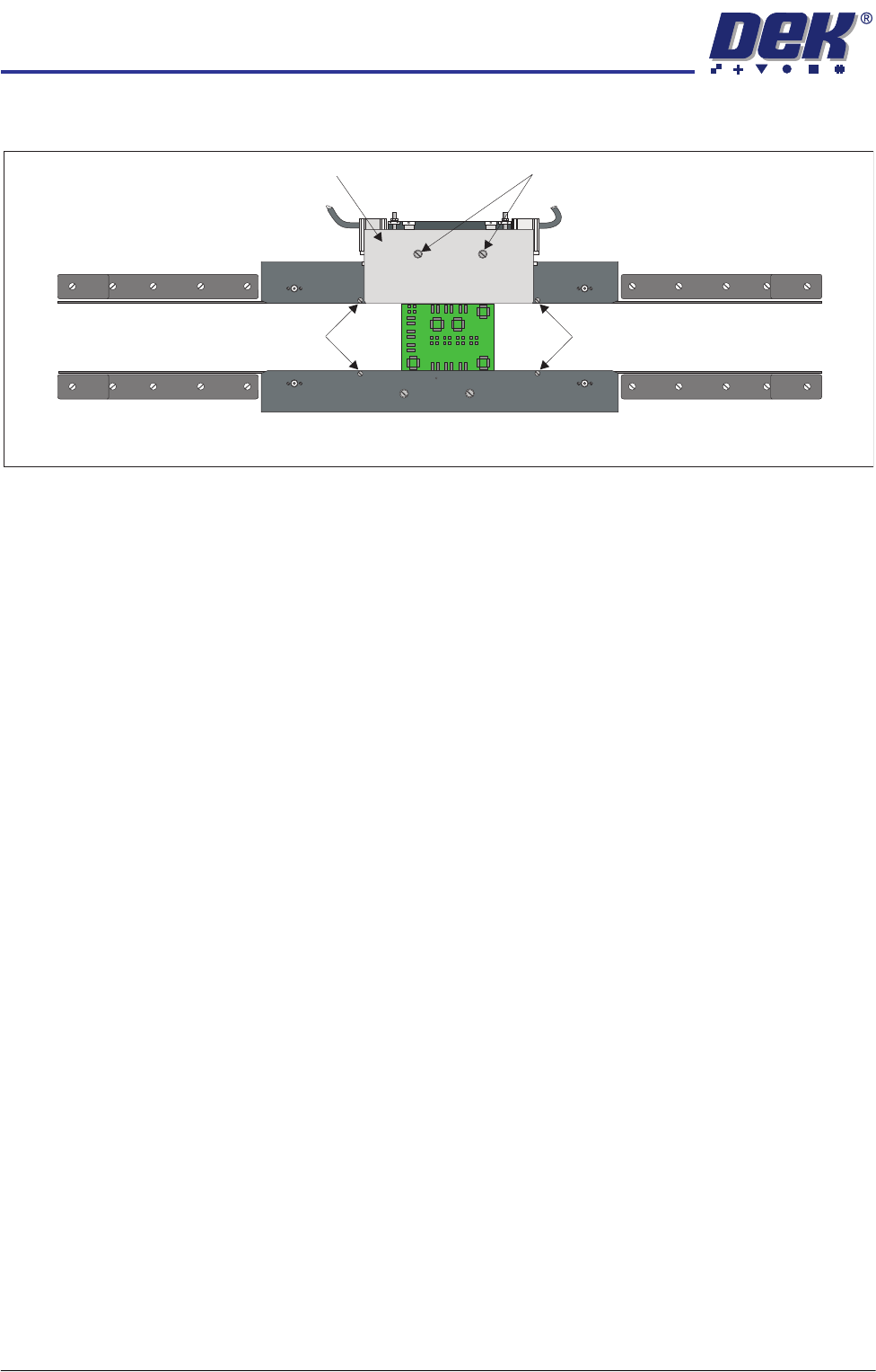
6. Slacken the two rear snugger plate securing screws.
7. Place a product board centrally between the snuggers.
8. Close the front printhead cover.
9. Press the System button.
10. Select Maintenance.
11. Select Diagnostics.
12. Use Next or Previous to highlight Rail System.
13. Select Select Module.
14. Use Next or Previous to highlight Toggle Board Clamp.
15. Select Run Diagnost.
16. The edge of the rear snugger plate aligns with the edge of the board.
17. Open the front printhead cover.
18. Tighten the two rear snugger plate securing screws.
19. Close the front printhead cover.
20. Press the System button.
21. Select Run Diagnost.
22. Open the front printhead cover.
23. Remove the product board from the machine.
24. Refit the screen.
25. Close the front printhead cover.
26. Press the System button.
27. Select Exit.
28. Select Exit.
29. Select Back.
Home Position
Rail Width Check
Ensure that the board clamps are fitted and that the Board Clamp Setting
procedure (this section refers) has been completed before carrying out the
following procedure:
1. Select Open Cover Commands.
Downstop Screws
Downstop Screws
Rear Snugger Plate Rear Snugger Plate Securing Screws
Plan View of Rail System
TRANSPORT RAILS MODULE
ADJUSTMENTS AND SETTINGS
Chapter Issue 4 Jan 10 Technical Reference Manual 16.23
2. Select Carriage To Rear.
3. Select Unload Screen.
4. Open the front printhead cover.
5. Remove the screen from the machine.
6. Close the front printhead cover.
7. Press the System button.
8. Select Maintenance.
9. Select Diagnostics.
10. Use Next or Previous to highlight Rail System.
11. Select Select Module.
12. Ensure that Home Rail Width is highlighted.
13. Select Run Diagnost.
14. Select Adjust and set the board width to 250mm.
15. Select Exit.
16. Use Next or Previous to highlight Drive Rail to Board Width.
17. Select Run Diagnost.
18. Open the front printhead cover.
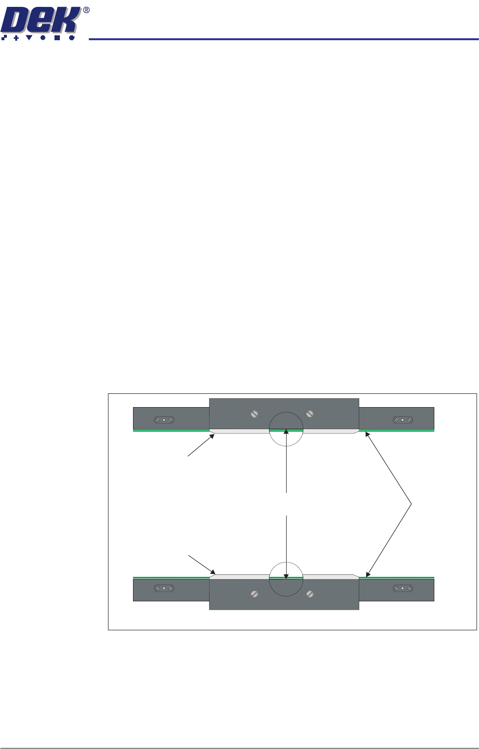
19. Place a vernier gauge above the transport belts in the centre of the board
clamps and check that the vernier reads 250.25mm ±0.10mm.
20. If the rail width is correct, go to Step 30.
21. Close the front printhead cover.
22. Press the System button.
23. Use Next or Previous to highlight Set Rail Board Width Calibration.
24. Select Run Diagnost to open the Rail Width Offset window.
250.25mm ±0.10mm
Rear Board Clamp
Plan View of Board Clamps
Transport Belts
Front Board Clamp
TRANSPORT RAILS MODULE
ADJUSTMENTS AND SETTINGS
16.24 Technical Reference Manual Chapter Issue 4 Jan 10
25. Use Incr. or Decr. to set the offset required to achieve the dimension in
Step 19.
NOTE
Increasing the offset increases the dimension between the rear rail and the
home position therefore, decreasing the width between the front and rear
rails.
26. Select Move.
27. Open the front printhead.
28. Recheck the measurement.
29. If the rail width is incorrect, close the front printhead cover, press the System
button and repeat Steps 25 to 28.
30. If the rail width is correct, close the front printhead cover, press the System
button and select Set.
31. Select Yes to save the information.
32. Use Next or Previous to highlight Cycle Board on Belts.
33. Select Run Diagnost.
34. Place a test board, that matches the rail width, on the transport rails.
35. Select Auto Board and ensure the board runs through the entire length of
the rail system for 10 complete cycles, without jamming or excessive clicking
of the board edges.
NOTE
If any jamming occurs investigate the position of the board/snugger clamps
before repeating the check.
36. Select Stop.
37. Remove the board from the transport rails.
38. Select Exit.
39. Select Exit.
40. Select Back.
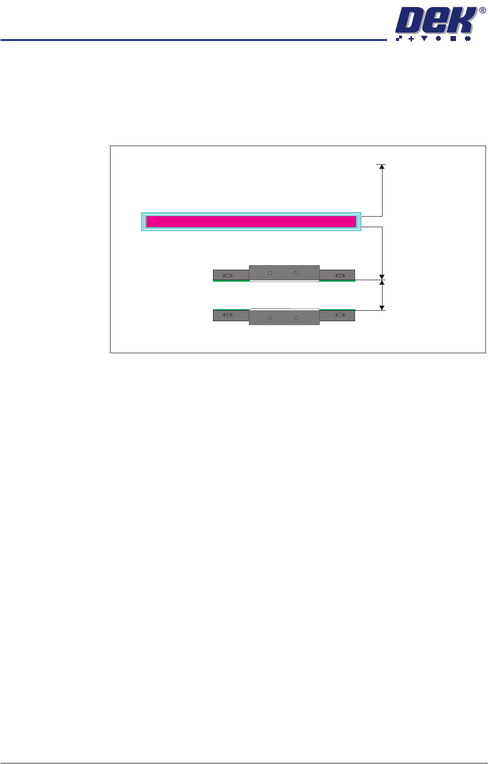
Plan View of Transport Rails (centre section)
Rear of Machine
Rail Width
RAIL WIDTH OFFSET 0.00 mm
±3.00mm