NPM Calibration Manual-En.pdf - 第88页
NPM Maint en anc e E di ti on 9.14 Accu racy Ve rificat ion EJM9BE-M B-09M-21 Page 9-87 9.14 A ccurac y Verification Thi s secti on descri bes the proc edures f or m easuri ng t he m achine’s pl acement accuracy and regi…
NPM
Maintenance Edition
9.13 Tray
Page 9-86 EJM9BE-MB-09M-21
17
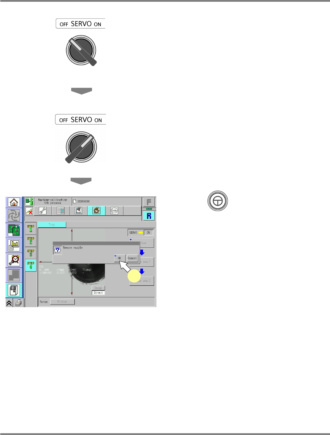
Turn OFF the servo switch.
18
Open the safety cover.
19
Detach the nozzles.
20
Close the safety cover.
21
Turn ON the servo switch.
22
Press + [OK].
•
After the head moves to the origin position,
the screen selected in step 16 is displayed.
UnitCalibTrayPos-08E00
22

NPM
Maintenance Edition
9.14 Accuracy Verification
EJM9BE-MB-09M-21 Page 9-87
9.14 Accuracy Verification
This section describes the procedures for measuring the machine’s placement accuracy and registering
the each-placement-position-angle offset by using that measured result.
9.14.1 Overview
1 Brief Description of Processes
The dedicated MCDATA (production program) is used for accuracy verification and registering
the each-placement-position-angle offset.
This work can be performed only by using the dedicated MCDATA.
When the each-angle offset is reflected, machine parameters in the machine will be rewritten.
You are recommended to save the current data beforehand just in case.
The following flow shows a brief description of processes.
1. Preparation for Production
Selection of MCDATA (Production Program)
Preparation for Placement, Checking of Pickup Positions, Setting of Nozzles
2. Checking and Reflection of Placement
Placement
Checking and Reflection of Placement Results
3. Checking of Placement Accuracy
Placement
Checking of Placement Results
2 Head Types, Work Details, and Components
The work to do varies according to the installed head pattern.
The each-angle offset will be reflected on Chip, Micro, General-purpose, and 3D (OP).
Chip: Reflected on 12 N and 8 N placement accuracy
Micro: Offset dedicated to 0402 components
General-purpose: Reflected on 2 N placement accuracy and general-purpose 8 N-ready
components (
12 or larger)
3D (OP): Reflected when the optional 3D sensor is used
Shown below are the nozzles to be used for each head.
Head Chip Micro General-purpose 3D
12-nozzle head 230CS x 12 230ZS x 12 --- ---
8-nozzle head 230C x 8 230Z x 8 184 x 2 184 x 2
2-nozzle head --- --- 1003 x 2 1005 x 2
NPM
Maintenance Edition
9.14 Accuracy Verification
Page 9-88 EJM9BE-MB-09M-21
Chip accuracy
Our specified jig chips are used for the placement check for chip components.
This jig chip is made of a ceramic material (as with an actual component) that is specially
plated.
It has enough shape stability to acquire the placement offset correctly.
Jig chip Model No. ERJJ02AAAAAV
Component shape 1.0 mm
×
0.5 mm Thickness 0.14 mm
It is indispensable to check the accuracy by the jig chips.
When mounting 0402 components, the offset dedicated to them will be used preferentially.
Before mounting 0402 components, it is recommended to register the offsets by angle with
0402R components and to verify the accuracy of them.
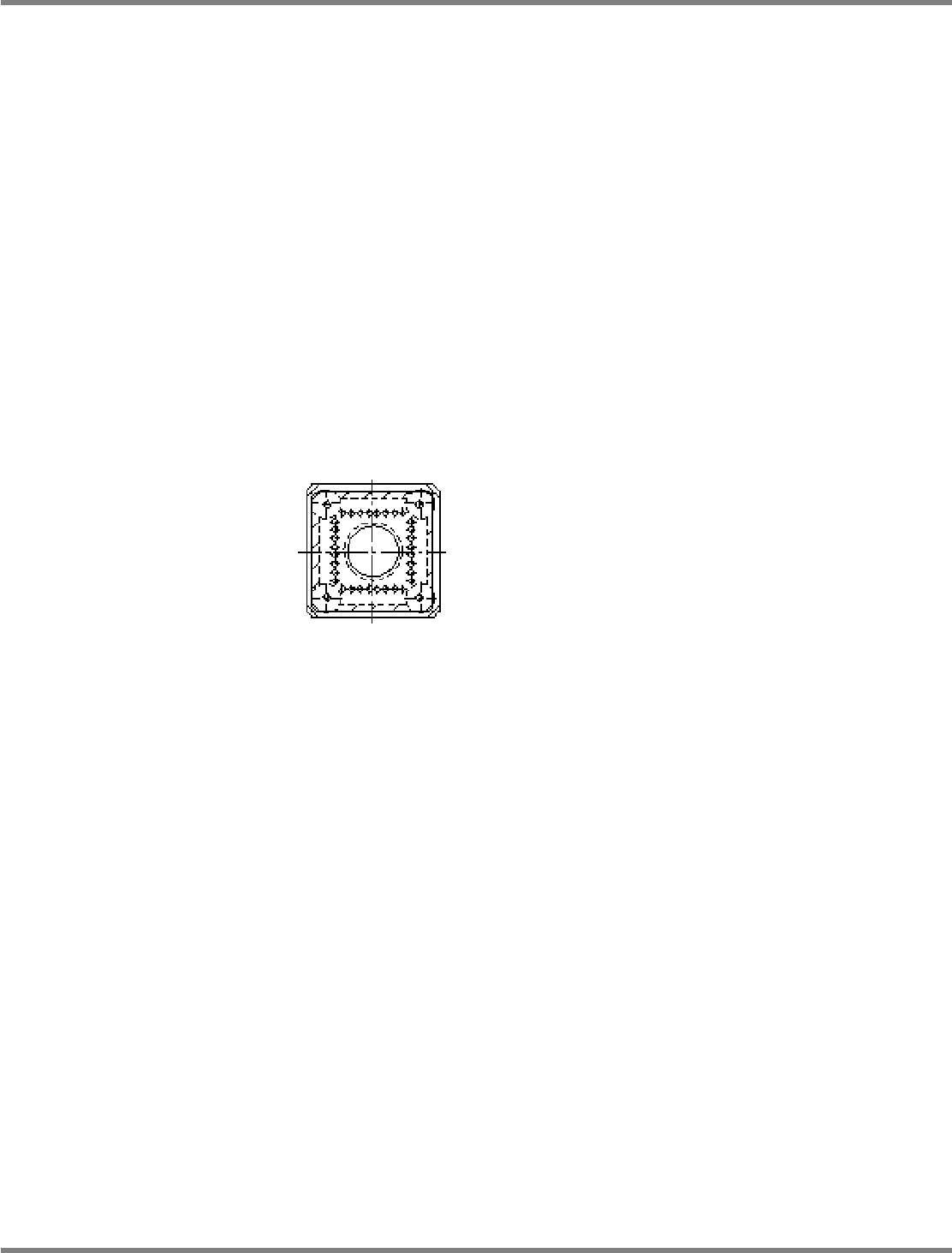
General-purpose accuracy and 3D (OP) accuracy
The dedicated JIG_BGA is used.
The metal plate where a BGA shape pattern is formed correctly is fixed in a resin case.
The accuracy is measured by placing each case.
JIG_BGA Model No. N610087876AA