NPM Calibration Manual-En.pdf - 第95页
NPM Maint en anc e E di ti on 9.14 Accu racy Ve rificat ion Page 9-94 EJM9BE-M B-09M-21 2 C h e ck in g an d Ref lec t i on of P l ac em en t Pl ace com ponents act uall y and check the resul t. ③ Placem en t 1 Press . 2…
NPM
Maintenance Edition
9.14 Accuracy Verification
EJM9BE-MB-09M-21 Page 9-93
•
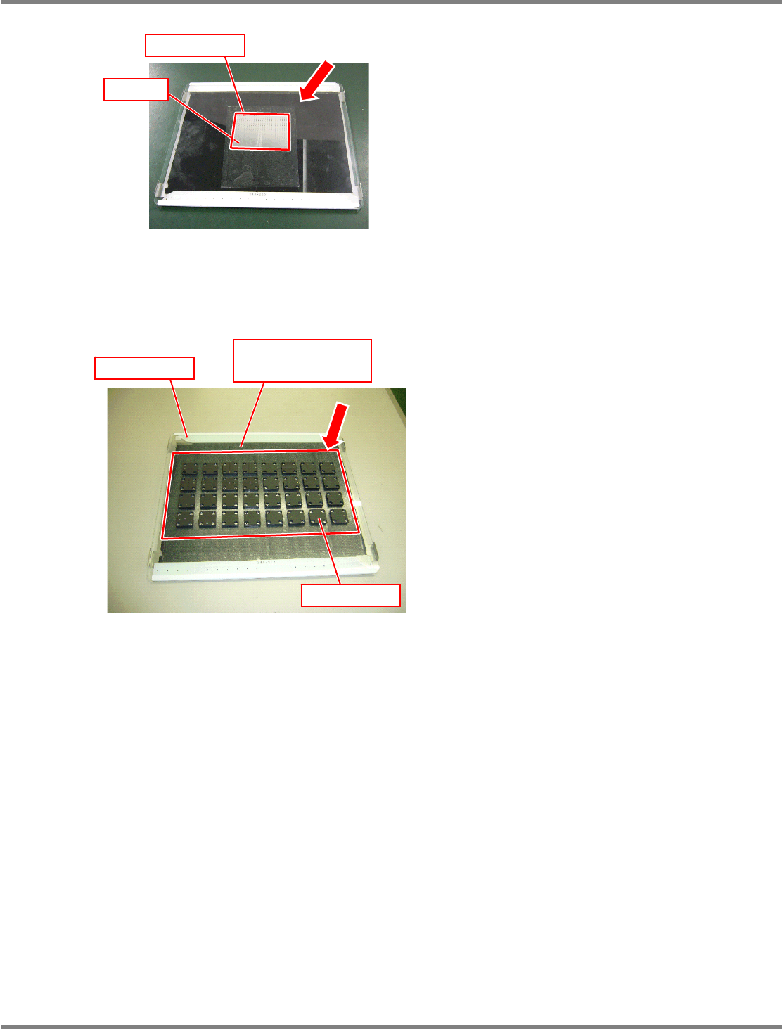
Affix double-faced tape to the glass PCB.
Roughly speaking, components are placed in
the frame shown left.
∗
Be careful not to affix it to the PCB marks on
both ends of the glass, and not to let air
bubbles in.
•
Set a background plate (a black sponge)
under the glass PCB.
Glass PCB after jig chips are placed
Chip component
Mirror
Glass PCB after JIG_BGA are placed
Glass PCB
Background plate
(Black sponge)
JG_BGA
NPM
Maintenance Edition
9.14 Accuracy Verification
Page 9-94 EJM9BE-MB-09M-21
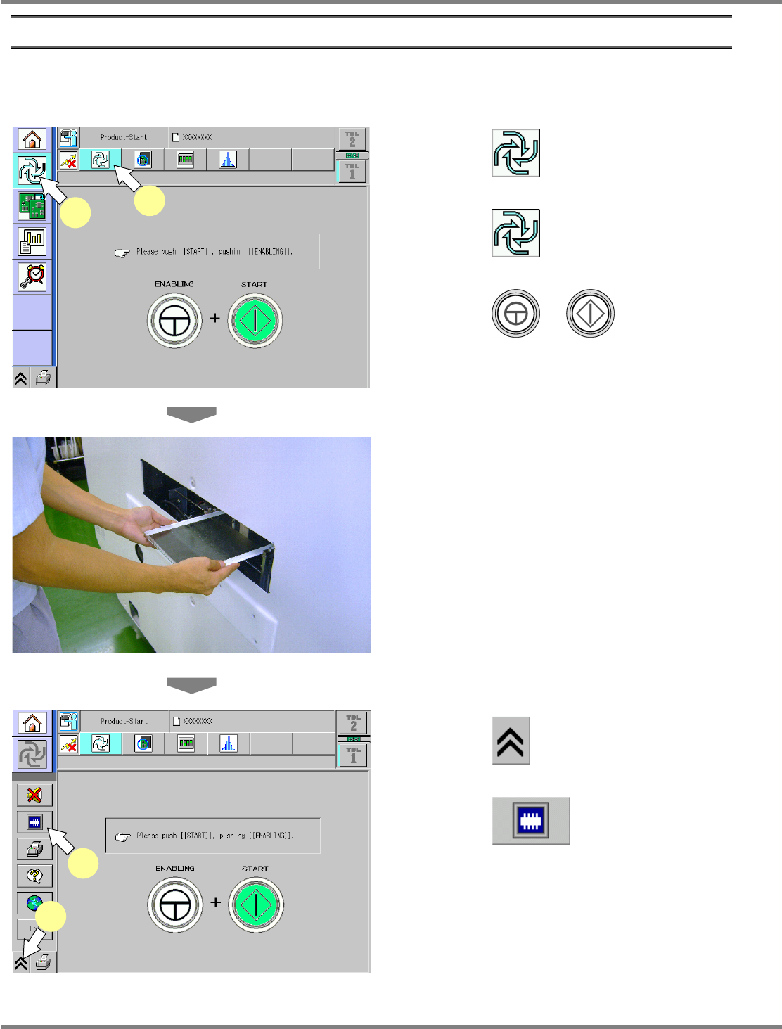
2 Checking and Reflection of Placement
Place components actually and check the result.
③
Placement
1
Press .
2
Press .
3
Press + .
∗
This step is the same as that for usual
preparation for production.
4
Load the glass PCB.
∗
After preparation for production is complete,
when the glass PCB is loaded, production
starts.
5
Press .
6
Press .
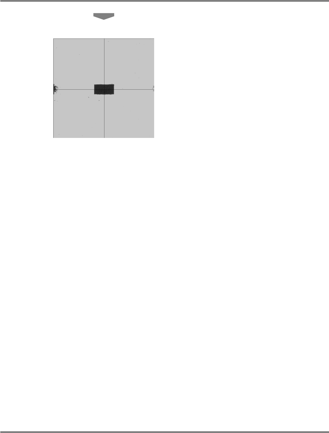
The head camera screen appears and you can
view the chip being measured.
ComEnabStart-01E02
1
2
ComEnabStartMenu-01J02-K
5
6
NPM
Maintenance Edition
9.14 Accuracy Verification
EJM9BE-MB-09M-21 Page 9-95
7
Place the components.
The components are placed by automatic
operation.
After all the components are placed, the head
camera starts measuring the placement
positions.