Infinity EX High Throughput Conveyor Module.pdf - 第14页
INFINITY EX HIGH THROUG HPUT CONVEY OR MODULE DRIVE S AND SE NSOR S 16.1 4 Technical Reference Manual C hapter Issue 1 Aug 02 DRIVES AND SENSORS Senso rs Motors Name T y pe Inpu ts Fun ction al De scr ipt ion Rail Lift e…
INFINITY
EX
HIGH THROUGHPUT CONVEYOR MODULE
MECHANICAL DETAIL
Chapter Issue 1 Aug 02 Technical Reference Manual 16.13
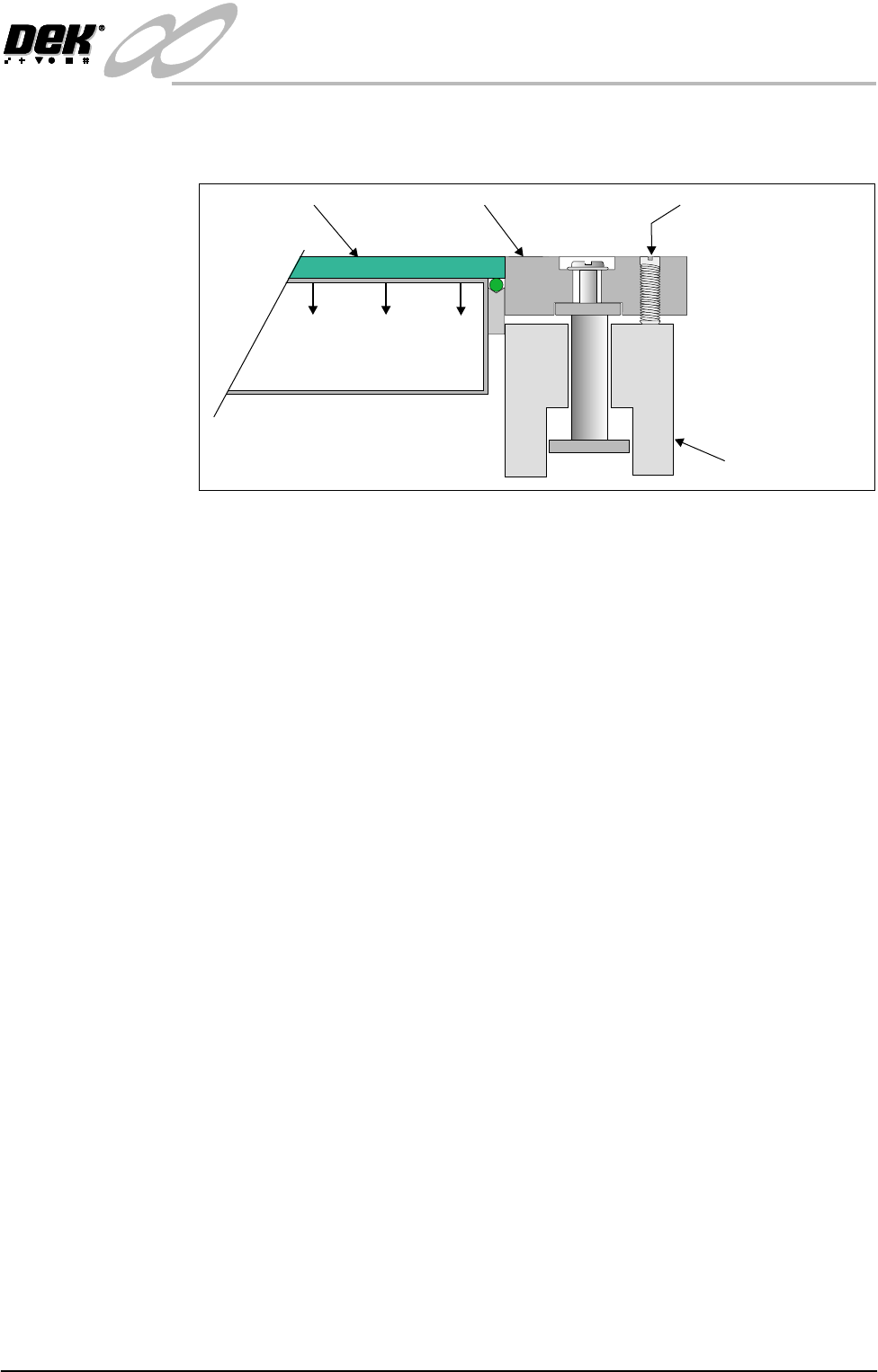
clamps are adjusted in height for different thicknesses of board by two grub
screws.
Figure 16-10 Foil-less Clamps
Adjustment Grub Screw
Rail
Foil-less ClampBoard
Vacuum Box

INFINITY
EX
HIGH THROUGHPUT CONVEYOR MODULE
DRIVES AND SENSORS
16.14 Technical Reference Manual Chapter Issue 1 Aug 02
DRIVES AND SENSORS
Sensors
Motors
Name Type Inputs Functional Description
Rail Lifted Left Through Beam Opto NextMove
Dig IN 3
Detects premature lifting of rail
Rail Lifted Right Through Beam Opto NextMove
Dig IN 4
Detects premature lifting of rail
Rail Home Through Beam Opto Stepper
Multiplexer
MUX2
Provides home position of moving rail thus
providing accurate board width settings
Board at Left Background Suppressed NextMove
Dig IN 16
Detects left side incoming/outgoing board
dependent upon machine pass through configuration
Board at Right Background Suppressed NextMove
Dig IN 17
Detects right side incoming/outgoing board
dependent upon machine pass through configuration
Left Auxiliary Rail Diffuse Opto M27PLC01-I/P1 Detects left side incoming/outgoing board
dependent upon machine pass through configuration
Right Auxiliary Rail Diffuse Opto M27PLC02-I/P1 Detects right side incoming/outgoing board
dependent upon machine pass through configuration
Name Type Functional Description
Moving Rail Drive Stepper Motor Moves the rear moving rail of the print station
conveyor in the Y direction
Front
Print Area Conveyor
Board Transport Belt Drive
DC Moving Coil Motor Turns the front transport belt, of the print station conveyor in the
clockwise or anti clockwise direction (dependent upon upline/
downline feed direction)
Rear
Print Area Conveyor
Board Transport Belt Drive
DC Moving Coil Motor Turns the rear transport belt, of the print station conveyor in the
clockwise or anti clockwise direction (dependent upon upline/
downline feed direction)
Front Left
Auxiliary Conveyor
Board Transport Belt Drive
DC Moving Coil Motor Turns the front transport belt, of the left auxiliary conveyor in the
clockwise or anti clockwise direction (dependent upon upline/
downline feed direction)
Rear Left
Auxiliary Conveyor
Board Transport Belt Drive
DC Moving Coil Motor Turns the rear transport belt, of the left auxiliary conveyor in the
clockwise or anti clockwise direction (dependent upon upline/
downline feed direction)
Front Right
Auxiliary Conveyor
Board Transport Belt Drive
DC Moving Coil Motor Turns the front transport belt, of the right auxiliary conveyor in
the clockwise or anti clockwise direction (dependent upon
upline/downline feed direction)
Rear Right
Auxiliary Conveyor
Board Transport Belt Drive
DC Moving Coil Motor Turns the rear transport belt, of the right auxiliary conveyor in
the clockwise or anti clockwise direction (dependent upon
upline/downline feed direction)
INFINITY
EX
HIGH THROUGHPUT CONVEYOR MODULE
DRIVES AND SENSORS
Chapter Issue 1 Aug 02 Technical Reference Manual 16.15
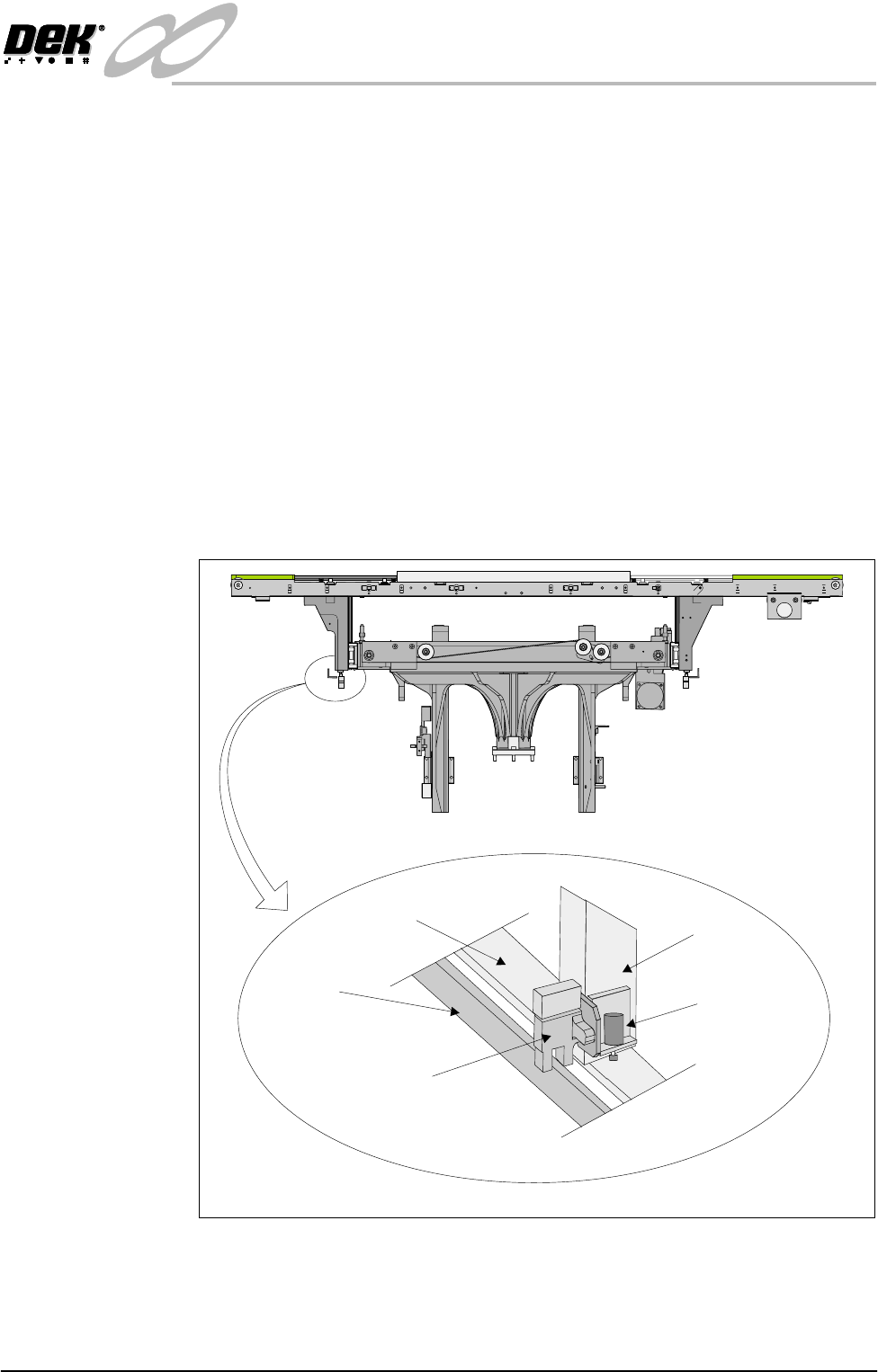
Rail Lifted Sensors The left and right rail lifted sensors are background suppression diffuse type
opto sensors.
These sensors are fitted to the bottom of the left and right moving rail support
arms of the print station rail. The sensor vanes are fitted to the entire length of
the rail stop bars. These sensors feed directly into NextMove card of the
machine PC.
The purpose of the rail lifted sensors is to detect premature lifting of the rail as
the rising table rises. This may occur if tooling or any other object was placed
under the rear rail. They are checked:
1. Immediately after the rail has moved to its new board width following
product file change.
2. When Run is pressed, before the camera moves to board stop position.
3. After printing to check that the rail is fully down before the next print cycle
can commence.
4. When the table moves to rail lift check height before moving to vision height.
Figure 16-11 Rail Lift Sensor Location
Rail Stop Bar
(Clatter Bar)
Opto Vane
Rail Lifted Left
Opto
Left Rail
Transport Leg
Shock Absorber
Enlarged View of Left Rail Opto
View on Front of Machine