Infinity EX High Throughput Conveyor Module.pdf - 第28页
INFINITY EX HIGH THROUG HPUT CONVEY OR MODULE ADJUS TMEN TS AND SE TTINGS 16.2 8 Technical Reference Manual C hapter Issue 1 Aug 02 1. Place a board on the ra ils cov ering the sensor . 2. T urn the sensiti vity control …
INFINITY
EX
HIGH THROUGHPUT CONVEYOR MODULE
ADJUSTMENTS AND SETTINGS
Chapter Issue 1 Aug 02 Technical Reference Manual 16.27
bracket.
3. Tighten the securing bolts.
4. Power up and run the machine, checking for correct operation of the sensor.
5. If coarse adjustment of the sensor is required, a further bracket mounting
hole is available inboard.
Sensitivity
Adjustment
The print station Board at Left/Right sensors are a background suppression
sensor type. The sensor switching threshold can be adjusted by means of a
sensitivity control switch mounted on the face of the sensor. This ensures that
when a board is fed into the machine (via transport belts) the sensor output
switches to ON.
To achieve an optimum setting carry out the following procedure:
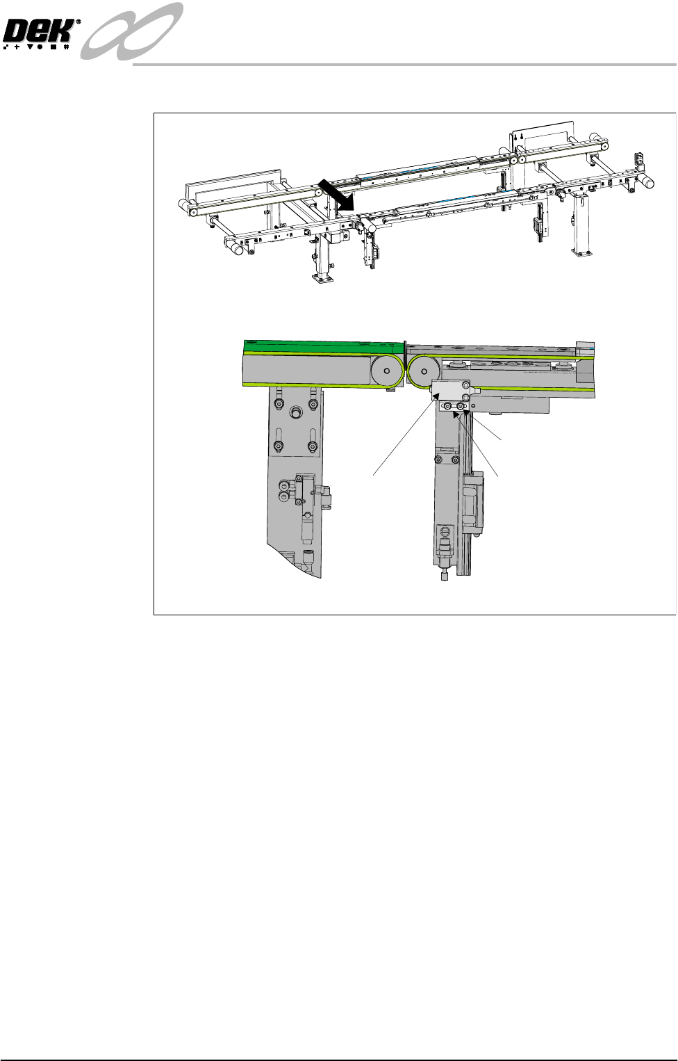
A
Front View on High Throughput Conveyor
View on Arrow ‘A’
Sensor
Sensor Mounting Bracket
Mounting Bracket Bolts
INFINITY
EX
HIGH THROUGHPUT CONVEYOR MODULE
ADJUSTMENTS AND SETTINGS
16.28 Technical Reference Manual Chapter Issue 1 Aug 02
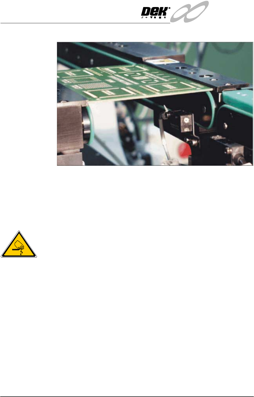
1. Place a board on the rails covering the sensor.
2. Turn the sensitivity control fully anti-clockwise, ensure that the LED is
extinguished.
3. Re-adjust the sensitivity control clockwise until the LED illuminates. Con-
tinue turning the sensitivity control clockwise for one more graduation.
4. Remove the board from the rails and confirm that the LED extinguishes.
Print Station Front Rail Parallelism
WARNING
BOARD CLAMPS. EXTREME CARE MUST BE EXERCISED WHEN
WORKING IN THE TOOLING AREA OF THE MACHINE TO AVOID
INJURY. THE FOILS ON THE FRONT AND REAR BOARD CLAMPS
ARE VERY SHARP.
NOTE
Ensure Camera X Axis Parallelism (Camera and Vision Systems Module Chap-
ter refers) has been carried out prior to commencing this procedure.
1. In Camera Diagnostics, home the Camera X and Y axes. Select Drive to
Board Stop Position the camera carriage is driven to the rear of the front rail.
2. Raise the printhead and insert the head prop.
3. Select Close System to power down the machine.
4. Carry out either of the following:
a. Remove the camera (refer to Camera and Vision Systems Module Chapter,
Camera and Optical Unit Assembly Removal).
b. If available fit a spare camera assembly bearing to the right hand end of
the camera rail.
INFINITY
EX
HIGH THROUGHPUT CONVEYOR MODULE
ADJUSTMENTS AND SETTINGS
Chapter Issue 1 Aug 02 Technical Reference Manual 16.29
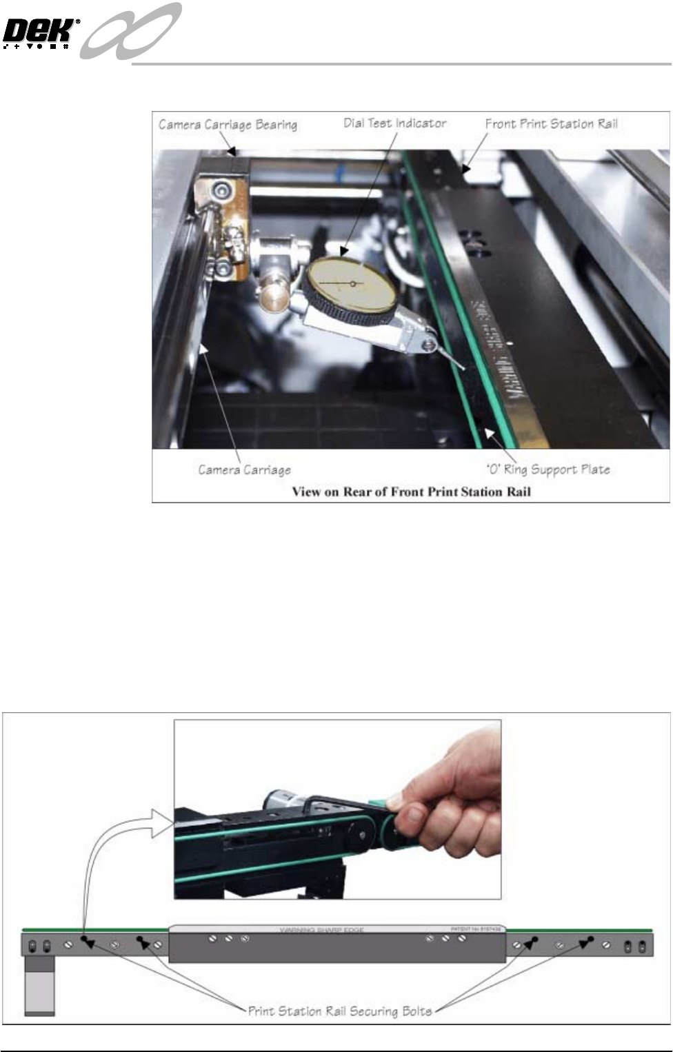
5. Fit a Dial Test Indicator (D.T.I.) to the camera carriage bearing.
6. Using the D.T.I. check the front rail parallelism to camera carriage rail over
the length of the 'O' ring support plate to ±0.2mm.
7. If adjustment is necessary, carry out the following:
a. Slacken the four rail securing bolts (two each side) adjust the front rail as
required. Tighten the bolts, re-check the parallelism.
b. When the adjustment is complete, remove each bolt disturbed (one at a
time), apply suitable locking compound and fully tighten. Remove the
D.T.I.