Infinity EX High Throughput Conveyor Module.pdf - 第23页
INFINITY EX HIGH THROUG HPUT CONVE YOR MODULE ADJUS TMENT S AND SET TINGS Chapter Issu e 1 Aug 02 Technical Reference Manual 16.23 11. Select Adjust , the following windo w is displayed: 12. Using the Next , Pre vious , …
INFINITY
EX
HIGH THROUGHPUT CONVEYOR MODULE
ADJUSTMENTS AND SETTINGS
16.22 Technical Reference Manual Chapter Issue 1 Aug 02
ADJUSTMENTS AND SETTINGS
Rail Lifted Sensors 1. From the run menu, select Maint.
2. Select Diagnost.
3. Select Rising Table. Select Select Module.
4. Select Home Rising Table. Select Run Diagnost, ensure the table moves
to its home position.
5. Select Exit.
6. Select Rail System. Select Select Module.
7. Select Home Rail Width. Select Run Diagnost, ensure the rear rail moves
to its home position.
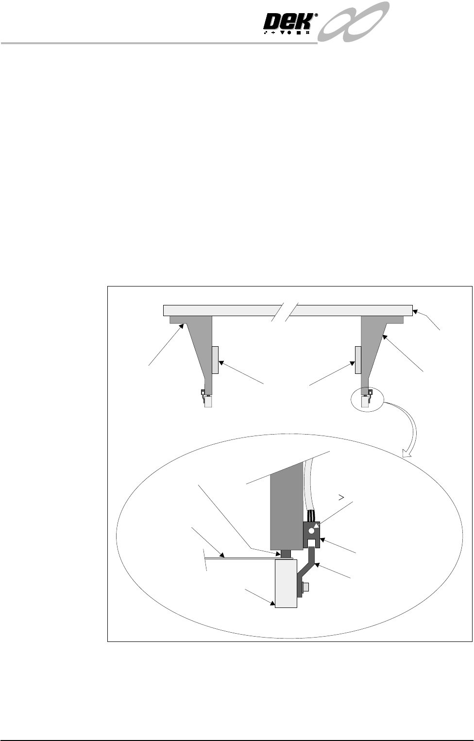
8. Place a 0.5mm feeler gauge between the shock absorber on the rear right rail
transport leg and the rail stop bar (clatter bar). Adjust the vane bracket using
a 2.5mm Allen key, so that the sensor LED is On with a 0.5mm feeler gauge
fitted and Off with a 0.7mm feeler gauge fitted. Lock adjusting screws.
9. Repeat Step 8 for left hand end of rear rail.
10.Select Drive Rail To Board Width. Select Run Diagnost.
Right Rail
Support Bracket
Main Rear
Rail
Front View of Rail System
Left Rail
Support Bracket
Feeler Gauge
(0.5mm)
Rail Stop Bar
Opto Vane
Bracket
Opto
Shock Absorber
Light Extinguishes
when Sensor lifted
0.5mm
Linear Rail
Enlarged View of Right Rail Opto

INFINITY
EX
HIGH THROUGHPUT CONVEYOR MODULE
ADJUSTMENTS AND SETTINGS
Chapter Issue 1 Aug 02 Technical Reference Manual 16.23
11.Select Adjust, the following window is displayed:
12.Using the Next, Previous, Incr. and Decr. keys, set the Board Width to
50mm.
13.Select Exit.
14.Select Drive Rail To Board Width, the rear rail moves to the new board
width.
15.Repeat Steps 8 and 9 for setting the vane at the 50mm width. Lock adjusting
screws.
16.Select Home Rail Width. Select Run Diagnost, ensure the rear rail moves
to its home position.
17.Repeat Steps 8 and 9 at the home position, adjust vanes if necessary.
18.Select Cycle Rails. Select Run Diagnost, ensure the sensors LED are On
over the full travel of the rail.
Rail Width Home
Sensor
The rail width home sensor is used to find the home position of the moving rail
and is described in detail in the Sequences section (Homing Sequence) of this
chapter.
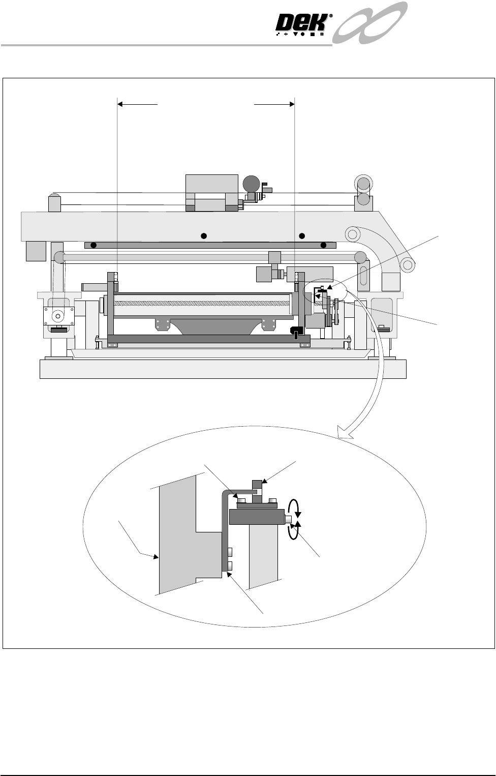
The sensor is mounted on an adjustable bracket which enables the position
between the front and rear rails to be set at 508.5mm - 508.7mm, (measured
between the inside edges of both rails, when the moving rail is in the home
position).
A fine adjustment can be made to the set rail dimension by slackening the sensor
forward securing screw and turning the home sensor adjustment screw (Figure
Rail Home Setting refers) in accordance with the table below.
NOTE
Rail width home sensor checks are also required if rail parallelism adjustments
are carried out
Rail System Test Parameters
BOARD WIDTH
CYCLE COUNT
250.0
50
mm
Cycles
Home Sensor Screw Adjustment Set Rail Dimension
1 full turn clockwise + 0.5mm
1 full turn anti-clockwise - 0.5mm
INFINITY
EX
HIGH THROUGHPUT CONVEYOR MODULE
ADJUSTMENTS AND SETTINGS
16.24 Technical Reference Manual Chapter Issue 1 Aug 02
Figure 16-16 Rail Width Board Sensor Setting
Auxiliary Conveyor Sensors
Positional
Adjustment
If heavy boards are being printed and causing damage to the conveyor board
stops, adjustment of the position of the sensor can be carried out to minimise this
effect. To adjust the position of the sensor carry out the following:
1. Power down the machine.
Rail Home
Sensor
Rail Home
Opto Flag
(home vane)
Betweeninsideedgesof rails
View on Right Hand Side of Machine
508.5mm - 508.7 mm
Adjustable Through
Beam Opto Sensor
Home Sensor Adjustment
Screw (0.5mm Pitched
Thread)
Rear Rail
Opto Flag
Sensor Forward Securing Screw
Enlarged View of Rail Home Position Sensor