Infinity EX High Throughput Conveyor Module.pdf - 第33页
INFINITY EX HIGH THROUG HPUT CONVE YOR MODULE ADJUS TMENT S AND SET TINGS Chapter Issu e 1 Aug 02 Technical Reference Manual 16.33 to lo wer machine frame securing bolts. 3. Adjust the position of the con veyor to obtain…
INFINITY
EX
HIGH THROUGHPUT CONVEYOR MODULE
ADJUSTMENTS AND SETTINGS
16.32 Technical Reference Manual Chapter Issue 1 Aug 02
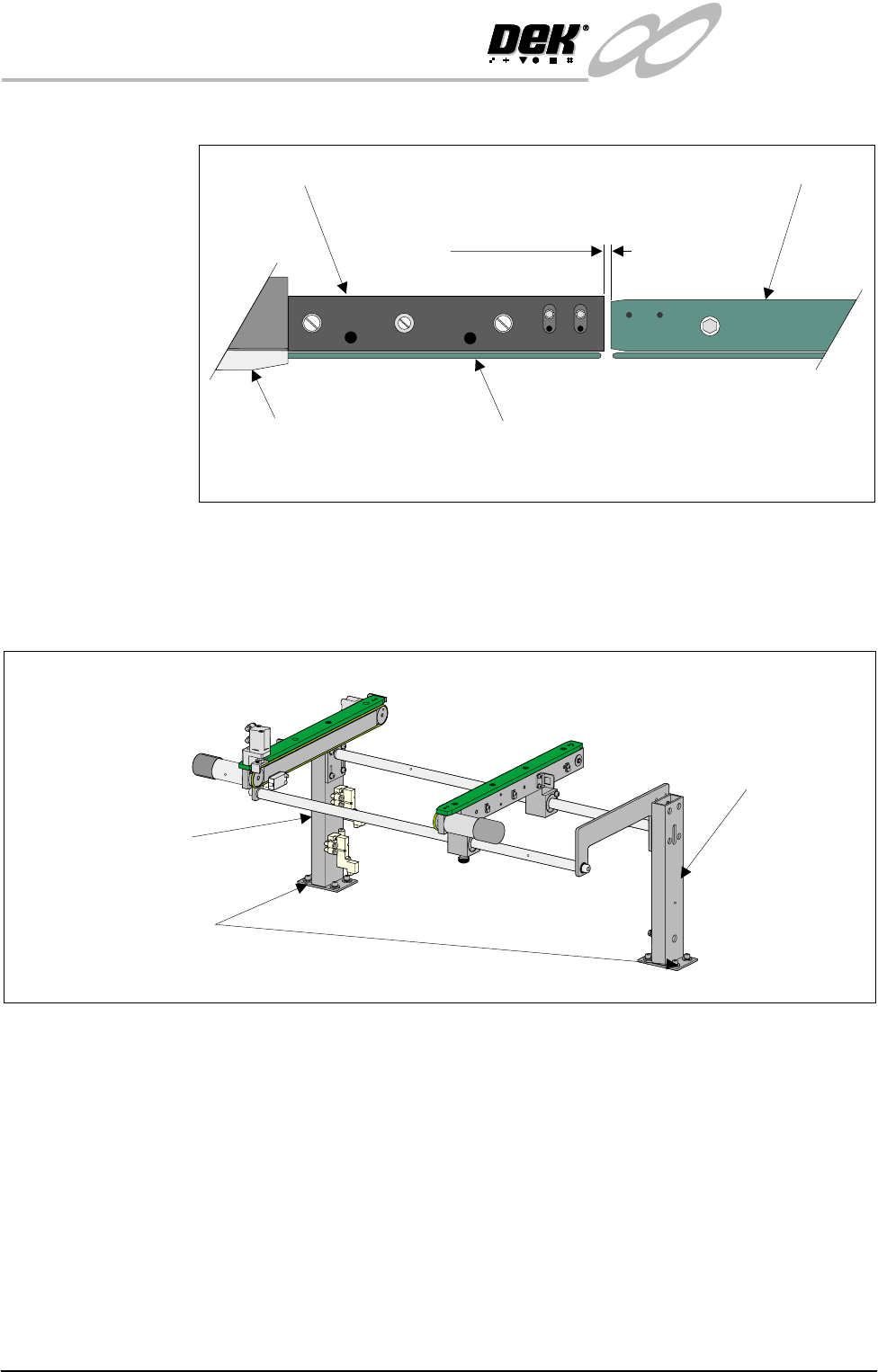
station and the auxiliary conveyors (in four positions) is 3.0 ± 0.5mm.
2. If adjustment is required, carry out the following:
a. Right hand conveyor - loosen the eight auxiliary conveyor rail support
securing bolts (four bolts on each support) that secure the auxiliary
conveyor to the machine lower frame.
b. Left hand conveyor - loosen the eight auxiliary conveyor left hand frame
Board Clamp
Board Transport Rail
Auxiliary Conveyor
Print Station
Plan View on Print Station and Auxiliary Rails
5157438
3.0mm +/- 0.5mm
Rear View of Right Auxiliary Conveyor
Front Auxiliary Conveyor
Rail Support
Rear Auxiliary Conveyor
Rail Support
Rail Support to Main Frame
Bolts (4 bolts in 2 positions)
INFINITY
EX
HIGH THROUGHPUT CONVEYOR MODULE
ADJUSTMENTS AND SETTINGS
Chapter Issue 1 Aug 02 Technical Reference Manual 16.33
to lower machine frame securing bolts.
3. Adjust the position of the conveyor to obtain the 3.0 ± 0.5mm gap.
4. Re-tighten the securing bolts disturbed in Step 2a or 2b and re-check the gap
measurement.
5. On completion, carry out Front Auxiliary Conveyor Rail Parallelism check.
Auxiliary Conveyor Levelling
Right Hand
Conveyor
To check and if required adjust the right hand auxiliary conveyor levelling, carry
out the following procedure:
1. Adjust the right hand auxiliary conveyor rail width to approximately
250mm.
2. Place a Board Clamp Setting Plate Pt No 140403 onto the auxiliary conveyor
transport belts.
3. Place a spirit level on top of the setting plate and check the levelness of the
conveyor in the X and Y planes.
4. If adjustment is required, carry out the following:
a. Loosen the four bolts that secure the auxiliary conveyor shaft guide plate
to the rear rail support and the four bolts that secure the rail bracket to front
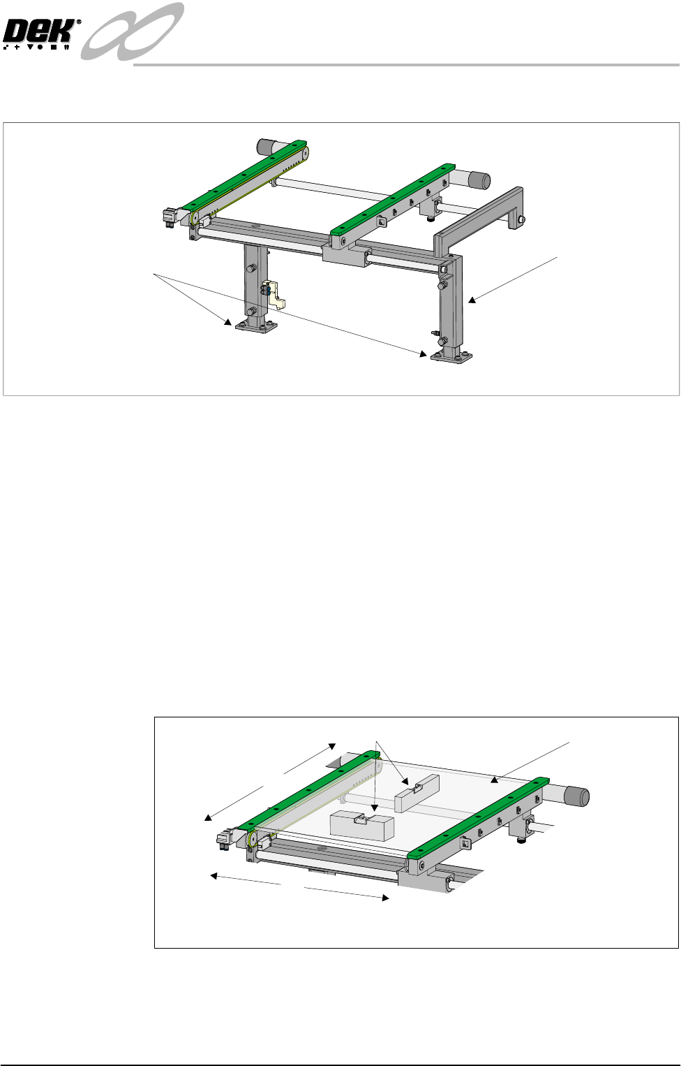
Rear View of Left Auxiliary Conveyor
Left Hand Auxiliary
Conveyor Frame
Conveyor Frame to
Machine Main Frame
(4 bolts in 2 positions)
X
Y
Board Clamp
Setting Plate
View on Auxiliary Conveyor
Spirit Level
INFINITY
EX
HIGH THROUGHPUT CONVEYOR MODULE
ADJUSTMENTS AND SETTINGS
16.34 Technical Reference Manual Chapter Issue 1 Aug 02
rail support.
b. Carefully adjust the height of the auxiliary conveyor rails to achieve
conveyor levelness.
c. Re-tighten the rail bracket and shaft guide plate securing bolts and repeat
the check.
Left Hand Conveyor To check and if required adjust the left hand auxiliary conveyor levelling, carry
out the following procedure:
1. Adjust the left hand auxiliary conveyor rail width to approximately 250mm.
2. Place a Board Clamp Setting Plate Pt No 140403 onto the auxiliary conveyor
transport belts.
3. Place a spirit level on top of the setting plate and check the levelness of the
conveyor in the X and Y planes.
4. If adjustment in the X plane is required, carry out the following (see graphic
overleaf):
a. Loosen the three hexagonal headed bolts, two on the inner face and one on
the outer face of the front upright of the conveyor frame.
b. Using the two hexagonal headed bolts on the inner face of the rear upright
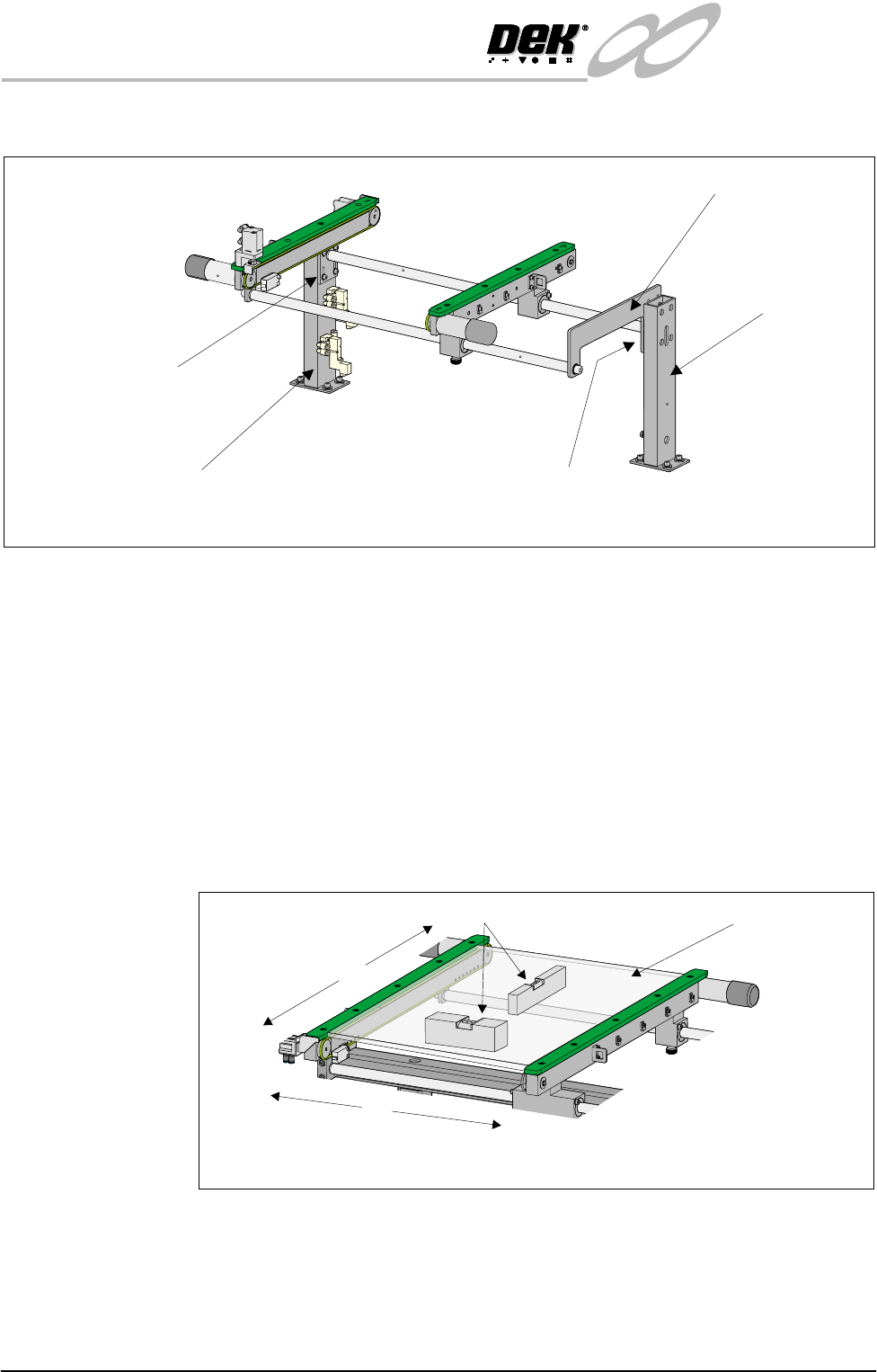
Rear View of Right Auxiliary Conveyor
Front Auxiliary Conveyor
Rail Support
Rear Auxiliary Conveyor
Rail Support
Shaft Guide Plate
Shaft Guide Plate to Rear
Rail Support Bolts (4 off)
Rail Bracket to Front
Rail Support Bolts
(in 4 positions)
X
Y
Board Clamp
Setting Plate
View on Auxiliary Conveyor
Spirit Level