Infinity EX High Throughput Conveyor Module.pdf - 第18页
INFINITY EX HIGH THROUG HPUT CONVEY OR MODULE SEQUEN CES 16.1 8 Technical Reference Manual C hapter Issue 1 Aug 02 SEQUENCES Homin g Sequ ence The print station rail is homed during machine initializ ation only , (during…
INFINITY
EX
HIGH THROUGHPUT CONVEYOR MODULE
DRIVES AND SENSORS
Chapter Issue 1 Aug 02 Technical Reference Manual 16.17
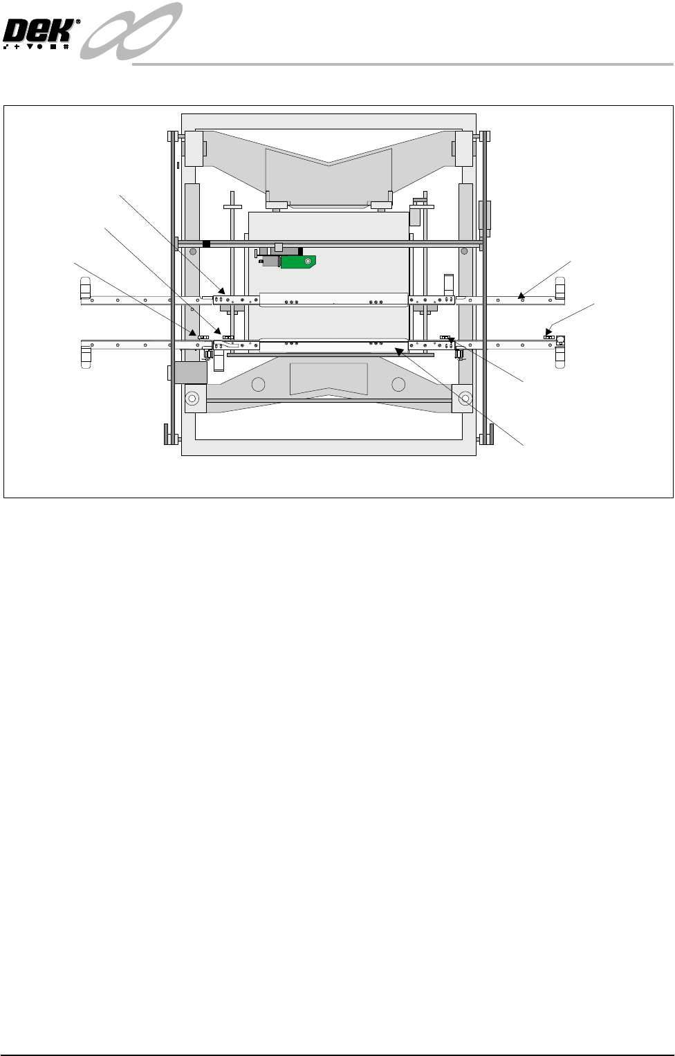
Figure 16-13 Board at Left/Right Opto Sensor Locations
Auxiliary Rail
Sensors
The auxiliary rail sensors are diffuse opto type sensors.
There are two sensors, one on each of the auxiliary conveyors. As the machine
is bi-directional the position of each sensor is reversed when the pass thru
direction is changed.
Each sensor is used to detect a board on the conveyor. The belt motors stop when
a board is detected unless, the downline machine, (which can either be the print
station or an external machine, depending on the conveyor and the pass thru
direction) is free to receive it.
Boardat RightSensor
Boardat Left Sensor
FrontPrintStation Rail
Plan View on Machine - Printhead Removed
PULNIX
TM-6EX
K
E
Y
E
N
C
E
P
Z
-
4
2
L
K
E
Y
E
N
C
E
P
Z
-
4
2
L
K
E
Y
E
N
C
E
P
Z
-
4
2
L
K
E
Y
E
N
C
E
P
Z
-
4
2
L
K
E
Y
E
N
C
E
P
Z
-
4
2
L
K
E
Y
E
N
C
E
P
Z
-
4
2
L
WARNING SHARP EDGE
PATENTNo 5157438
WARNING SHARP EDGE
PATENTNo 5157438
K
E
Y
E
N
C
E
P
Z
-
4
2
L
Auxiliary Rail (4 Positions)
Rear Print Sation Rail
Auxiliary Rail
Sensor
Auxiliary Rail
Sensor
INFINITY
EX
HIGH THROUGHPUT CONVEYOR MODULE
SEQUENCES
16.18 Technical Reference Manual Chapter Issue 1 Aug 02
SEQUENCES
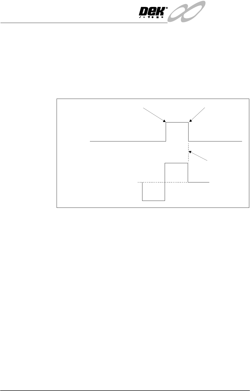
Homing Sequence The print station rail is homed during machine initialization only, (during power-
up or upon exiting diagnostics).
When the home command is received the rear print station rail is driven (in the
reverse direction) to the rear of the machine until the home vane, attached to it,
is detected by the rail home sensor. Upon detection (sensor ON) the motor is
driven in the opposite direction until the vane clears the home sensor and the
motor stops (sensor OFF).
Figure 16-14 Rail Timing Diagram
Rail Positioning There is a fixed relationship between steps of the stepper drive motor and rail
movement (in mm) due to the gearing ratios and pitch of the driving leadscrews.
Therefore, when a width is selected this is multiplied by the steps/mm factor and
sent to the stepper drive system.
All positions are relative to the home position.
Machine Sequences The high throughput conveyor system can operate in four modes, selectable on
the M27 located at the rear of the machine.
• Single Stage Normal
• Single Stage Fast
• Three Stage Normal
• Three Stage Fast
NOTE
1. Large apertures in the product board can cause the sensors to activate/
deactivate. In the event of false triggering, select Normal Mode.
2. In the sequences below, the machine is described as working in left to right
operation.
Single Stage Normal In single stage normal mode the auxiliary rails and the print station rail are
configured as one rail. The rail system transports the board from the upline
Home Position
Fwd
Stepper
Motor
Home
Sensor
0
Stopped
Rev
Vane leaves sensor
Vane enters sensor
INFINITY
EX
HIGH THROUGHPUT CONVEYOR MODULE
SEQUENCES
Chapter Issue 1 Aug 02 Technical Reference Manual 16.19
machine, into the machine, where the board is positioned, clamped and printed.
After printing, the board is transferred to the downline machine. A signal to the
upline machine, to dispense another board, is sent when the leading edge of the
board switches the ‘board present’ sensor on the downline machine. If the
downline machine has a board at the sensor, the conveyor board stop activates
to prevent the board leaving the print station. In single stage normal mode, only
one board can be in the machine at any one time.
Single Stage Fast In single stage fast mode the signal to the upline machine, to dispense another
board, is sent when the trailing edge of the printed board passes the board at right
sensor on the print station. In the event of the downline machine being busy, the
board is stopped at the end of the print station. In single stage fast mode, two
boards can be in the machine at the same time (one entering the machine on the
upline auxiliary conveyor as the printed board is exiting on the downline
auxiliary conveyor).
NOTE
If the downline transfer time is greater than the machine cycle time (displayed
on the machine MMI), single stage normal mode must be selected to prevent two
boards on the downline conveyor at the same time.
Three Stage Normal In three stage normal mode the upline auxiliary conveyor transports Board 1 to
the print station conveyor where the board is processed. With Board 1 in print
position, Board 2 is dispensed from the upline machine. When Board 2 arrives
at the sensor, at the end of the upline auxiliary conveyor, the transport belts stop.
K
E
Y
E
N
C
E
P
Z
-4
2
L
Board 1
K
E
Y
E
N
C
E
P
Z
-
4
2
L
K
E
Y
E
N
C
E
P
Z
-
4
2
L
K
E
Y
E
N
C
E
P
Z
-
4
2
L
WARNING SHARP EDGE
PATENT No 5157438
WARNING SHARP EDGE
PATENT No 5157438
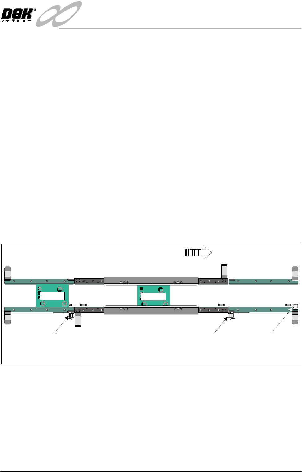
Print StationConveyor
Board Stop
Downline Conveyor
Board Stop
Upline Conveyor
Board Stop
Plan View of Board Positioning with Downline Machine Delay (Three Stage Mode)
Board Direction from Left to Right
K
E
Y
E
N
C
E
P
Z
-
4
2
L
K
E
Y
E
N
C
E
P
Z
-
4
2
L
Board 2