Infinity EX High Throughput Conveyor Module.pdf - 第56页
INFINITY EX HIGH THROUG HPUT CONVEY OR MODULE ADJUS TMEN TS AND SE TTINGS 16.5 6 Technical Reference Manual C hapter Issue 1 Aug 02 28. Refit the e xternal pneumatic connection to the external services panel. 29. Power u…
INFINITY
EX
HIGH THROUGHPUT CONVEYOR MODULE
ADJUSTMENTS AND SETTINGS
Chapter Issue 1 Aug 02 Technical Reference Manual 16.55
configured as the print station board stop.
23.Gain access to the M27 HTC Controller enclosure.
24.Remove the four M27 enclosure securing screws.
25. Pull the M27 enclosure from its chassis mount and lower on the chassis hinge
to access the rear panel socket array.
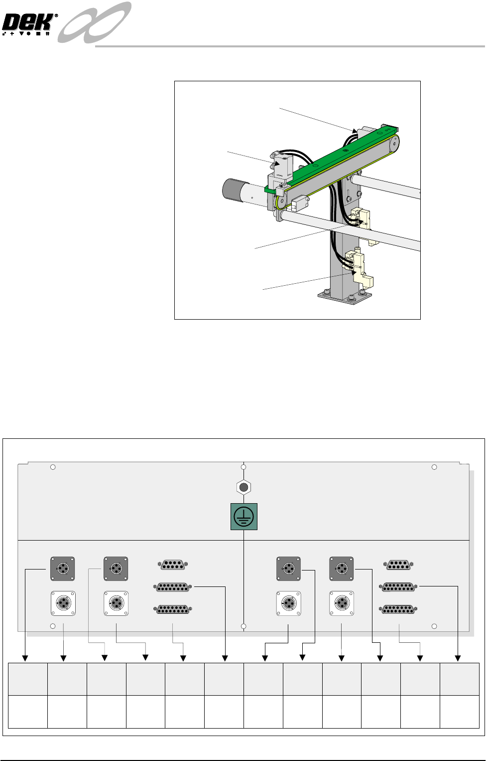
26. To configure the M27 enclosure for left to right throughput direction, connect
the enclosure as shown in the graphic below:
27.On completion, refit the M27 enclosure.
Pneumatic Solenoid
(SOL 03)
Pneumatic Solenoid
(SOL 01)
Downline Conveyor
Board Stop
Upline Board Stop
Now Confgured as Print Station Board Stop
M27SK04 M27SK12M27SK18 M27SK19
M27SK08 (L/H)M27SK20 (L/H) M27SK08 (R/H)M27SK21 (R/H)
LANE A (LEFT) LANE A (RIGHT)
M27SK01 (L/H) M27SK01 (R/H)
M27SK02 (L/H) M27SK02 (R/H)
M27SK03 M27SK11
Inverted View on Rear of 3-Stage Conveyor Controller M27
M27SK20
(L/H)
M27PL20
(SOL 02)
N/C
N/C
N/C
M27PL08
(SOL 01)
M27PL21
(SOL 03)
M27PL04/
M27PL18
M27PL12/
M27PL19
M27PL01
(Loom
160622)
M27PL02
(Loom
160622)
M27PL02
(Loom
160645 or
160631)
M27PL01
(Loom
160643 or
160631)
M27SK04
M27SK08
(L/H)
M27SK18
M27SK01
(L/H)
M27SK02
(L/H)
M27SK12
M27SK21
(R/H)
M27SK19
M27SK08
(R/H)
M27SK01
(R/H)
M27SK02
(R/H)

INFINITY
EX
HIGH THROUGHPUT CONVEYOR MODULE
ADJUSTMENTS AND SETTINGS
16.56 Technical Reference Manual Chapter Issue 1 Aug 02
28.Refit the external pneumatic connection to the external services panel.
29.Power up and initialize the machine. If required, remove the head prop and
lower the head.
30.In Set Prefs menu, ensure the Transport Mode option is selected to Left to
Right.
INFINITY
EX
HIGH THROUGHPUT CONVEYOR MODULE
CALIBRATIONS
Chapter Issue 1 Aug 02 Technical Reference Manual 16.57
CALIBRATIONS
Board Transport Belt Speed (Auxiliary Rails)
The board transport belt speeds of the two auxiliary rails are controlled by the
M27 and are not adjustable. The belt speed can be measured using a tachometer
on the input or output pulley, check the speed to be approximately 500mm/sec
(30m/sec).
Board Transport Belt Speed (Print Station Rail)
WARNING
LETHAL VOLTAGE. DANGEROUS VOLTAGES EXIST IN THIS
EQUIPMENT. ENSURE ALL ELECTRONIC COVERS AND MAIN
MACHINE COVERS ARE FITTED BEFORE OPERATING THIS
EQUIPMENT.
The front and rear board transport belts, of the print station rail, are driven
independently by two variable speed motors. Inevitably one motor drives faster
than the other motor. It is necessary to calibrate these motors so that they drive
at the same speed in either direction. Therefore, the faster motor must be
calibrated to match the slower motors speed.
The speed of both the belt motors is controlled by a MultiMove card situated in
the machine control enclosure and utilizes Pulse Width Modulation (PWM).
This is achieved by controlling the period of the ON control pulse provided by
the MultiMove control card. The pulse repetition rate is fixed at 125Hz.
The belt speed is measured using a tachometer on the underside of the input or
output pulley and adjusted by using the Belt Speed Calibration Page in the
machine diagnostics.
NOTE
For belt speed calibration set up see Calibration Procedure of this section. For
detailed information on access and use of the diagnostics module refer to the
Diagnostics chapter of the machine’s User manual.
Motor speed software parameters is listed in the following table:
Calibration
Procedure
1. In Diagnostics, select Rail System.
2. Select Belt Speed Calibration, the following window is displayed:
3. Using a tachometer fitted with the surface speed test wheel, positioned on the
Name Maximum Minimum Default Increment
Front L to R Speed 64000 0 32000 1
Rear L to R Speed 64000 0 32000 1
Front R to L Speed 64000 0 32000 1
Rear R to L Speed 64000 0 32000 1
SEMI 2
Belt Speed Calibration
50000
50000
63999
63999
FRONT L TO R SPEED
FRONT R TO L SPEED
REAR L TO R SPEED
REAR R TO L SPEED