Infinity EX High Throughput Conveyor Module.pdf - 第37页
INFINITY EX HIGH THROUG HPUT CONVE YOR MODULE ADJUS TMENT S AND SET TINGS Chapter Issu e 1 Aug 02 Technical Reference Manual 16.37 that secure the a uxiliary con ve yor to the mac hine lo wer fram e. 7. Carefully a djust…
INFINITY
EX
HIGH THROUGHPUT CONVEYOR MODULE
ADJUSTMENTS AND SETTINGS
16.36 Technical Reference Manual Chapter Issue 1 Aug 02
c. Tighten bolt C loosened in Step 5a and repeat the check.
Auxiliary Conveyor Rail Parallelism
WARNING
BOARD CLAMPS. EXTREME CARE MUST BE EXERCISED WHEN
WORKING IN THE TOOLING AREA OF THE MACHINE TO AVOID
INJURY. THE FOILS ON THE FRONT AND REAR BOARD CLAMPS
ARE VERY SHARP.
Front Rail To check and if required adjust the auxiliary conveyors front rail parallelism,
carry out the following procedure:
NOTE
The parallelism of the auxiliary conveyors rails is dependent on the front and
rear print station rails being parallel. Therefore, before any adjustment is
carried out an assessment of the parallelism of the print station rails must be
carried out.
1. In Rail System Diagnostics, select Adjust and alter board width to 250mm.
2. Select Drive Rail to Board Width. The rails are driven to the board width
selected.
3. Adjust the both auxiliary conveyor rail widths to approximately 250mm.
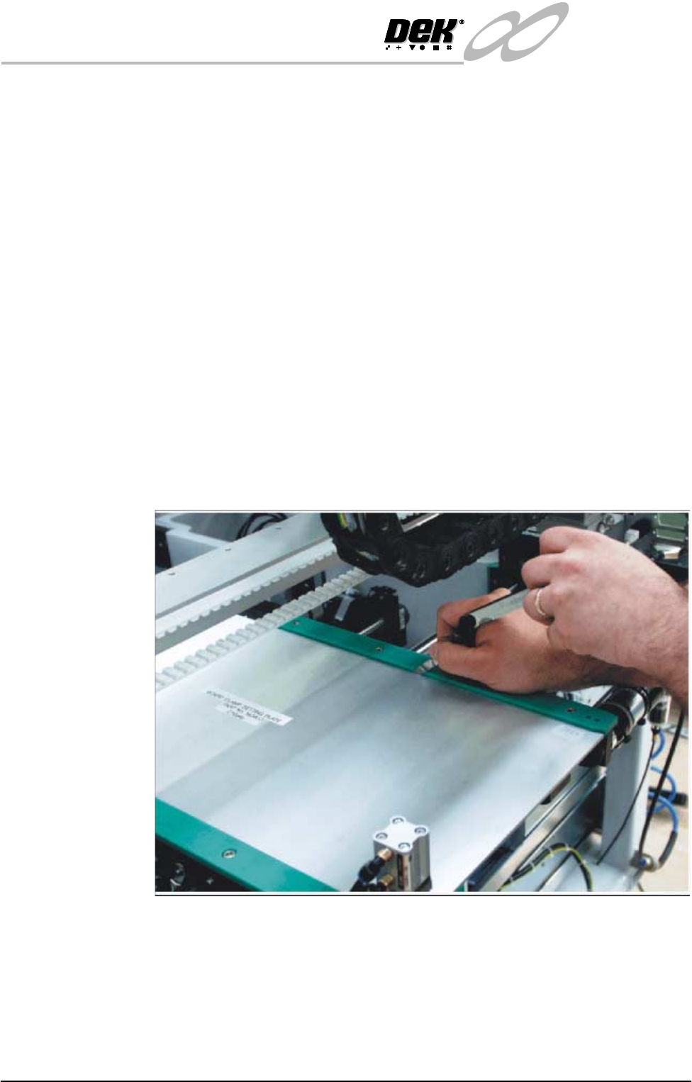
4. Place one of the Board Clamp Setting Plates Pt No 140403 onto the print
station transport belts.
5. Manually slide the setting plate back and forth from the print station to the
right hand auxiliary conveyor, ensuring the plate moves freely without
binding or jamming.
6. If adjustment is required on the right hand auxiliary conveyor, loosen the
eight auxiliary conveyor rails support securing bolts (four on each support)
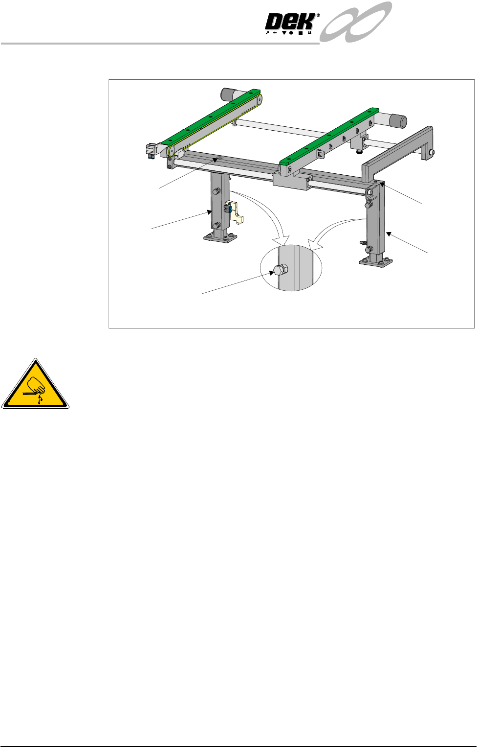
Rear View of Left Hand Auxiliary Conveyor
Bolt C on Outer Face
Of Conveyor Frame Uprights
Rear Upright of
Conveyor Frame
Front Upright of
Conveyor Frame
Height Adjustment
Grub Screw
Height Adjustment
Grub Screw
INFINITY
EX
HIGH THROUGHPUT CONVEYOR MODULE
ADJUSTMENTS AND SETTINGS
Chapter Issue 1 Aug 02 Technical Reference Manual 16.37
that secure the auxiliary conveyor to the machine lower frame.
7. Carefully adjust the conveyor to obtain front rail parallelism with the print
station front rail, whilst maintaining the gap between the auxiliary rail and
print station rail (refer to Auxiliary Rail to Print Station Gap section of this
chapter).
8. Re-tighten the securing bolts and re-check for parallelism.
9. Repeat Step 5 for the left hand auxiliary conveyor.
10.If adjustment is required left hand auxiliary conveyor, loosen eight auxiliary
conveyor frame securing bolts (four on each upright) that secure the con-
veyor to the machine lower frame.
11.Carefully adjust the conveyor to obtain front rail parallelism with the print
station front rail, whilst maintaining the gap between the auxiliary rail and
print station rail (refer to Auxiliary Rail to Print Station Gap section of this
chapter).
12.Re-tighten the bolts disturbed in Step 10 and re-check for parallelism.
Rear Rail To check and if required adjust the auxiliary conveyors rear rail parallelism,
carry out the following procedure:
NOTE
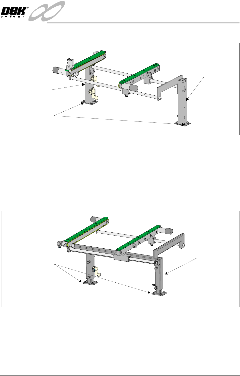
Rear View of Right Auxiliary Conveyor
Front Auxiliary Conveyor
Rail Support
Rear Auxiliary Conveyor
Rail Support
Rail Support to Main Frame
Bolts (4 off in 2 positions)
Rear View of Left Auxiliary Conveyor
Left Hand Auxiliary
Conveyor Frame
Conveyor Frame to
Machine Main Frame
(4 bolts in 2 positions)
INFINITY
EX
HIGH THROUGHPUT CONVEYOR MODULE
ADJUSTMENTS AND SETTINGS
16.38 Technical Reference Manual Chapter Issue 1 Aug 02
1. The parallelism of the auxiliary conveyors rails is dependent on the front and
rear print station rails being parallel. Therefore, before any adjustment is
carried out an assessment of the parallelism of the print station rails must be
carried out.
2. Ensure that the auxiliary conveyor front rail is in alignment with the print
station front rail before any adjustment of the auxiliary conveyor rear rail
parallelism (refer to Auxiliary Conveyor Rail Parallelism - Front Rail section
of this chapter).
1. In Rail System Diagnostics, select Adjust and alter board width to 250mm.
2. Select Drive Rail to Board Width. The rails are driven to the board width
selected.
3. Adjust the both auxiliary conveyor rail widths to approximately 250mm.
4. Using a Board Clamp Setting Plate Pt No 140403, place the plate on the right
hand auxiliary conveyor transport belts.
5. Place a 0.5mm feeler gauge between the plate and the green wear insert of
the auxiliary conveyor rear rail.
6. Adjust the auxiliary conveyor rail width until the feeler gauge fit is tight
between the plate and the green wear insert. Check the fit of the feeler gauge
along the whole length of the conveyor rail.
7. Remove the feeler gauge and manually move the plate in and out of the
machine along the conveyor transport belts, ensuring the plate moves freely
without binding or jamming.
For fine adjustment carry out the following: