M6_ServiceManual_e.pdf - 第15页
1 Installation 1-7 Viewed from the front Viewed from the rear ⑧ Lock the adjust foo t nut lastly. NOTE: The adjust foot nuts must be locked with a clos ed wrench (nom inal: 46mm ) or a single-head wrench. ⑨ Connect the p…
1 Installation
1-6
ACTION:
① Locate the machine to the specified place.
② Remove the followings: the bolt that locks the head in the X-axis beam, the metal fitting that locks the
X-axis (Scan Camera) and the nylon ties that prevent XY-axis movement. Check to see that the head
and the S-axis can move to the X direction and the X-axis beam can move to the Y direction manually.
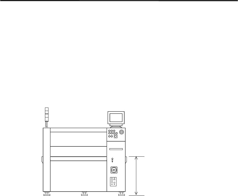
③ When the machine is installed stand alone, turn the adjust feet so that the PCB transfer height is the
same as the conveyor height (900±20mm (see Note)) of the reference equipment.
In the case of SMEMA interface spec., raise the conveyor height at 950±20mm by using lifting
blocks (thickness 50mm).
④ When the machine is connected to the Pre-process production line, adjust the PCB transfer height to
the conveyor rail height of the Pre-process.
)
Production Line
900+/- 20mm
or
950+/- 20mm(SMEMA)
NOTE: The height must be 890-920mm or 940-970mm in the case of CFB wagon spec.
NOTE: The adjust feet must be turned using a M30 single-head wrench (nominal: 46mm).
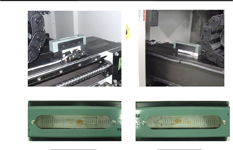
⑤ Place a leveler on the base of the machine. Set the position to the conveyor of the Pre-process finely
until the machine is leveled.
⑥ After the machine is positioned, make sure that a board runs smoothly between the pre-process and the
mounter conveyors.
⑦ Place a leveler on the X-axis beam and make a fine adjustment so that the difference in indicator when
the X-axis beam moves forward and backward will be within 1 division. ( To prevent a X-axis beam
distortion. )
1 Installation
1-7
Viewed from the front
Viewed from the rear
⑧ Lock the adjust foot nut lastly.
NOTE: The adjust foot nuts must be locked with a closed wrench (nominal: 46mm) or a single-head wrench.
⑨ Connect the power cable and ground line independently of other machines which may be a noise
source, such as a compressor and a welding machine.
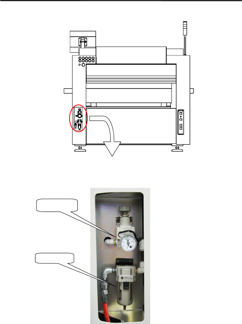
⑩ Connect an intake-side air coupler 65SN or 85SN (Nitto Kohki) or equivalent to the air regulator
coupler located on the rear of the machine. (Refer to the following page.) After the coupler is
connected, make sure that the air regulator indicates 0.49MPa (5.0 ㎏ f/c ㎡).
1 Installation
1-8
Air coupler
.
Intake-side air coupler
65SN/85SN (Nitto Kohki) or
equivalent
A
ir regulato
r