00900068-02_SM_ASM_ProcessLens_EN.pdf - 第23页
ASM Proces sLens Single - l ane 03/2020 Edit ion 23 3.4 Change the hi gh Ringlight assembly Ke y: 1) Screw (3 x) Figure 3- 11 : High Ringlight assembly (from below) Requirem ents: ● Machine is switche d off . ● It is adv…
ASM ProcessLens Single-lane 03/2020 Edition
22
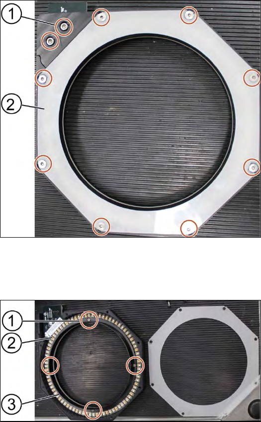
3.3.1 Change the low Ringlight board
Requirement:
● Low Ringlight assembly is dismantled.
Key:
1) Screw (10 x)
2) Cover
Figure 3-9: Low Ringlight assembly
1. Unscrew all screws (1) with an Allen key size 2.5.
2. Remove the cover (2) of the low Ringlight assembly
Key:
1) Screw (4 x)
2) Low Ringlight board
3) Plastic ring
Figure 3-10: Low Ringlight assembly (dismantled)
3. Unscrew the screws (1) using a Philips screwdriver.
4. Remove the plastic ring (3) and place it on the service table.
5. Change the low Ringlight board (2).
Installation
Follow the removal instructions in reverse order for installation.
ASM ProcessLens Single-lane 03/2020 Edition
23
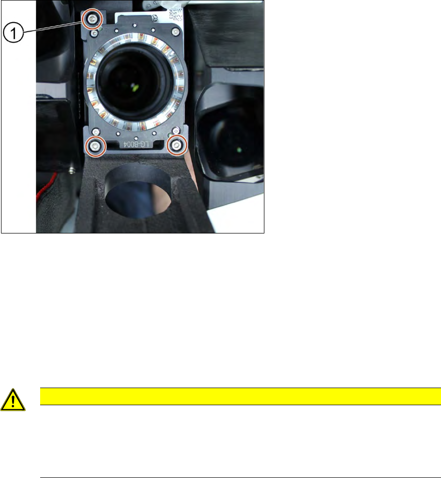
3.4 Change the high Ringlight assembly
Key:
1) Screw (3 x)
Figure 3-11: High Ringlight assembly (from below)
Requirements:
● Machine is switched off.
● It is advisable to dismantle the low Ringlight assembly as well for better access.
● Use a T shaped Allen key to carry out this task.
1. Unplug the connector
2. Unscrew the screws (1) using an Allen key size 2.5.
CAUTION
Small screws
The screws are very small. When the screws fall into the machine they may damage it.
Make sure the screws don’t fall into the machine.
Make sure no screw is left behind inside the machine.
Installation
Follow the removal instructions in reverse order for installation.

ASM ProcessLens Single-lane 03/2020 Edition
24
3.4.1 Change the high Ringlight board
Requirement:
● High Ringlight assembly is dismantled.
Key:
1) Connector
2) Screw (4 x) and washers
(4 x)
Figure 3-12: High Ringlight assembly (dismantled)
1. Unscrew the screws (1) using an Allen key size 1.5.
2. Separate the high Ringlight assembly.
CAUTION
Ringlight assembly
The two parts of the Ringlight assembly are hold together by two dowel pins. When
separating the two parts the Ringlight assembly may get damaged.
To separate the two parts, carefully pull the parts apart.
Key:
1) High Ringlight assembly
2) Dowel pin
3) High Ringlight board
4) Screw (6 x)
Figure 3-13: High Ringlight assembly (dismantled)
3. Unscrew the screws (4) that hold the high Ringlight board (3) in place using a Philips
screwdriver.
4. Remove the high Ringlight board (3).
Installation
Follow the removal instructions in reverse order for installation. Also observe the following
instructions: