00900068-02_SM_ASM_ProcessLens_EN.pdf - 第31页
ASM Proces sLens Single - l ane 03/2020 Edit ion 31 3.8 Change the enc oder reader at the x, y and z gantr y Require ment: ● Machine is switche d off . Ke y: 1) Screw (2 x) 2) Encoder Reader 3) Y scal e bar 4) Holder Fig…
ASM ProcessLens Single-lane 03/2020 Edition
30
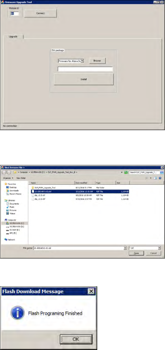
Figure 3-23: DLP Upgrade Tool
2. Enter the number 00 for the left DLP module or 01 for the right DLP module to test the left or
the right DLP module and press connect.
Figure 3-24: DLP Upgrade Tool
3. Click on the browse button to browse the needed .rbf file and open it.
4. Click on the install button to install the latest version.
5. The DLP module is now running the latest version.
ASM ProcessLens Single-lane 03/2020 Edition
31
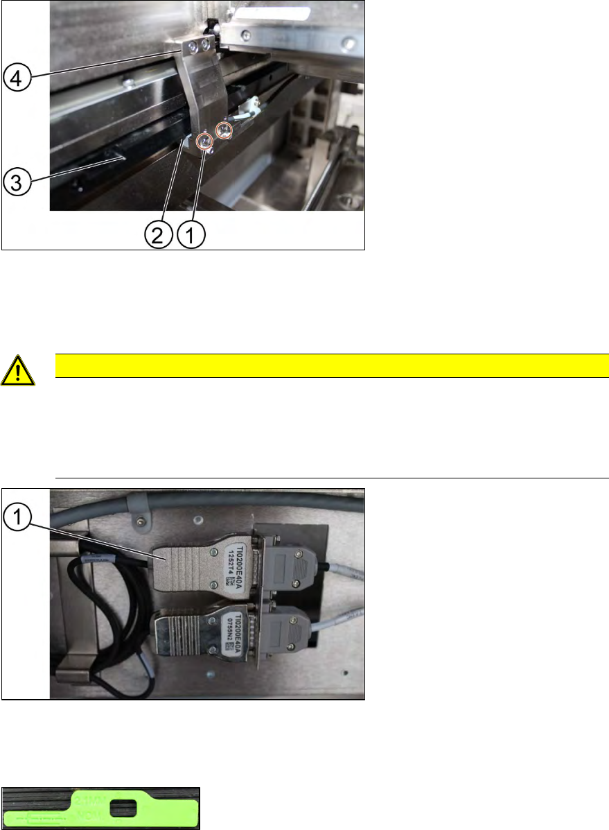
3.8 Change the encoder reader at the x, y and z gantry
Requirement:
● Machine is switched off.
Key:
1) Screw (2 x)
2) Encoder Reader
3) Y scale bar
4) Holder
Figure 3-25: Reader
1. Unscrew the screws (1) using an Allen T shaped Allen key size 2.0.
2. Carefully pull out the encoder reader (2).
CAUTION
The scale of the scale bars
Fingerprints or scratches damage the scale bars which then need to be exchanged.
Do not touch or scratch the scale of the scale bars.
Be careful when pulling out the reader and when putting it back again.
Key:
1) Encoder
Figure 3-26: Encoder
3. Change the reader including the encoder and all cables.
4. Replace the encoder and the reader.
Figure 3-27: Spacer
5. Check the gap between the reader and the scale bar by using the spacer provided.
ASM ProcessLens Single-lane 03/2020 Edition
32
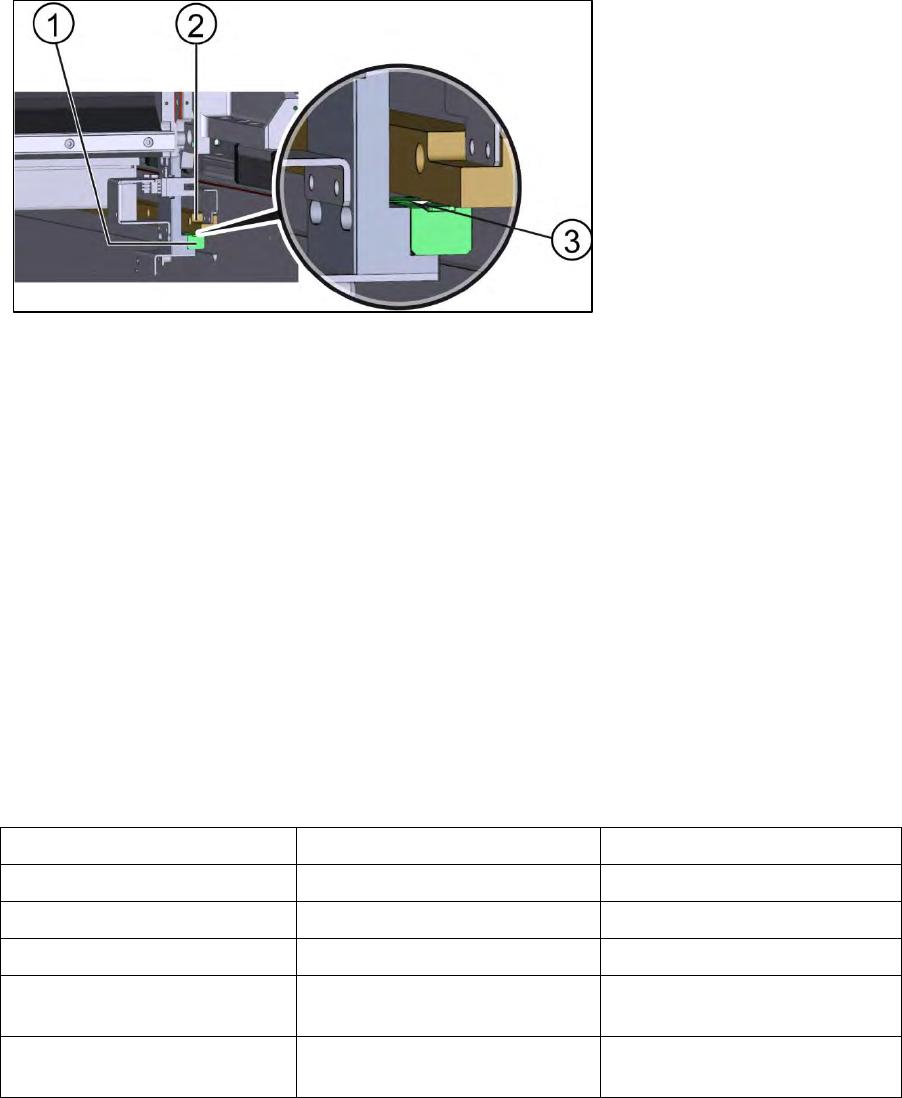
Figure 3-28: Position of spacer
Key:
1) Encoder reader
2) Y scale bar
3) Position of spacer
6. The gap between the reader and the scale bar must be 2.1 mm.
7. Calibrate the new reader. See the external Power Point file “Y1Y2 ENC install & adjust
procedure”.
8. Move the gantry slowly the whole travel range backwards. Whilst doing that check the light at
the indicator.
9. If the lights are not within the color range the holder needs adjustments. See 3.9 Color code for
the encoder readers.
10. Proceed the same way with all other encoder readers.
Installation
Follow the removal instructions in reverse order for installation.
3.9 Color code for the encoder readers
Color Indication Adjustment requirement
Purple Optimum set-up No
Blue Good set-up No
Green Good set-up No
Orange Acceptable set-up but below
recommendation level.
Yes, angle and gap.
Red Poor set-up, signal maybe too
low for reliable operation
Yes, angle and gap.
Table 3-2: Color code for the encoder readers