circuit of HS60.pdf - 第165页
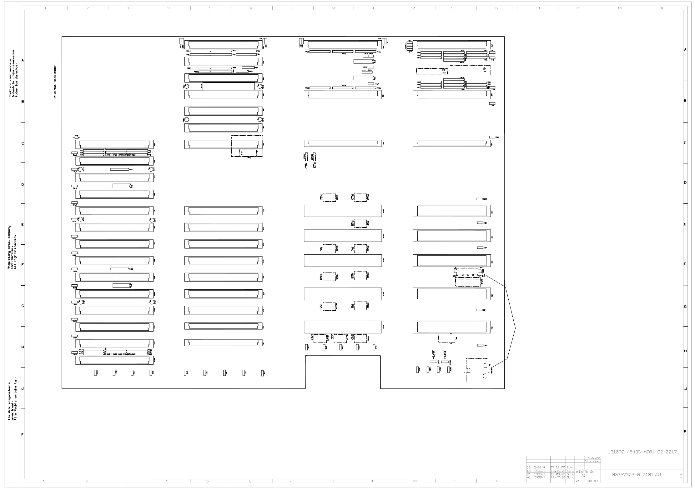
5 - 33 0035732 9-010 101ND 1 Backplane H S-60 Fan b) Space f or inspect ion label on si de 2 a) Space for identificati on label on si de 2 View onto si de 1 Soldering will be plac ed on side 2 Dash ed comp onen ts Stat. …
5 - 32
00350382-010101ND4 Adjustment unit, DP axis
Bauteilangaben nur zur Information
Weitergabe sowie Vervielfaeltigung dieser Unterlage, Ver-
wertung und Mitteilung ihres Inhalts nicht gestattet, soweit
nicht ausdruecklich zugestanden. Alle Rechte vorbehalten, ins-
besondere fuer den Fall der Patenterteilung oder GM-Eintragung.
1.
1.
1.
F
1
Doc. status
Product status
Function status
E
D
23
19.06.97
4
Comunicado como segredo empresarial. Reservados todos os direitos.
Confie a titre de secret d'entreprise. Tous droits reserves.
Proprietary data , company confidential . All rights reserved.
Confiado como secrete industrial. Nos reservamos todos los derechos.
C
B
A
1234
SMD Placement System SIPLACE HS60
00350382-010101ND4
5
Adjustment unit
678
1
+
=
1
F
E
D
567
C
B
8
A
DP axis
R2
R2R2
R2 R2
V2
V1
X2
X3
h1
h2
Status Modified NameDate Stand. Orig. Replacement for Replaced by
Date
Author
Check.
Sheet
Sh.
4
9
10
8
7
6
5
X2
2
3
11
4
2
3
X3
B1 motor
A2 motor
B2 motor
A1 motor
AGND
LED output signal
+ 15 V
+ 5 V
GND
A1-motor
A2-motor
B1-motor
AGND
B2-motor
DEMATIC
SIEMENS
SD EA
5 - 33
00357329-010101ND1 Backplane HS-60
Fan
b) Space for inspection label on side 2
a) Space for identification label on side 2
View onto side 1
Soldering
will be placed on side 2
Dashed components
Stat. Modified
Date Name
Dat.
Auth.
Check.
Stand.
Placement drawing page 1
HS60 backplane
Sheet
Sh.
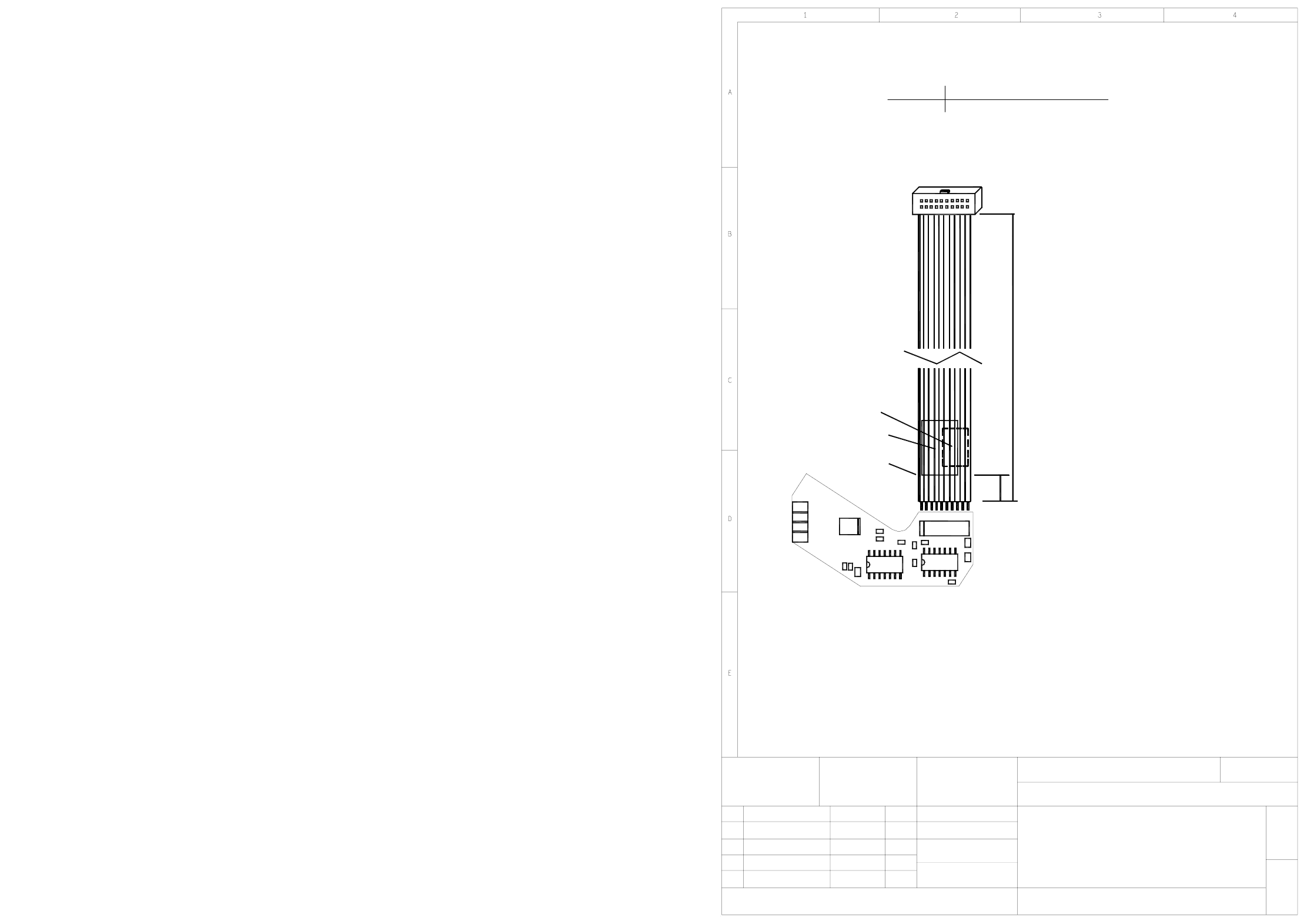
5 - 34
00359364-010101ND4 Adjustment unit 2 / reject circuit
Mounting diagram, component side
Adjustment drive 2
Reject circuit
00359364-010101ND4
1
1
SIEMENS AG
06.11.2001
06.11.200101
Stat. Modified Date Name
Date
Name
Sheet
Sh.
U2
R9
X4
X5
X3
X2
C4
C3
U3
R2
R1
B1, B2
A1
Pin 1
U1
C2
C6
X1
1
R5
R6
C5
10
R8R7
50.0mm
340.0mm
+5.0mm
-5.0mm
B1, B2:
A1:
X1
on the cable
On the back.
Label position:
AFO and WIP inspection labels.
50mm distance from cable end.
May be printed
readable, when X1 is on the left.
Identification label,
Cable, 05-1630-4
Assembly
X19 stepping motor boardoard 00344488
Connector
X1
readable, when X1 is on the right.