circuit of HS60.pdf - 第98页
3 - 3 0033589 1-010 201LD3 Servo u nit with out bo ards (Sh . 2 of 2) = SIEMENS AG + 3 5 2 4 6 1 Enable a21 = 0 Volt s analog Key Key a28 = 0 Volt s analog 8 12 3 Tacho-Y1 Enable A B C Weitergabe sowie Vervielfaeltigung …
3 - 2
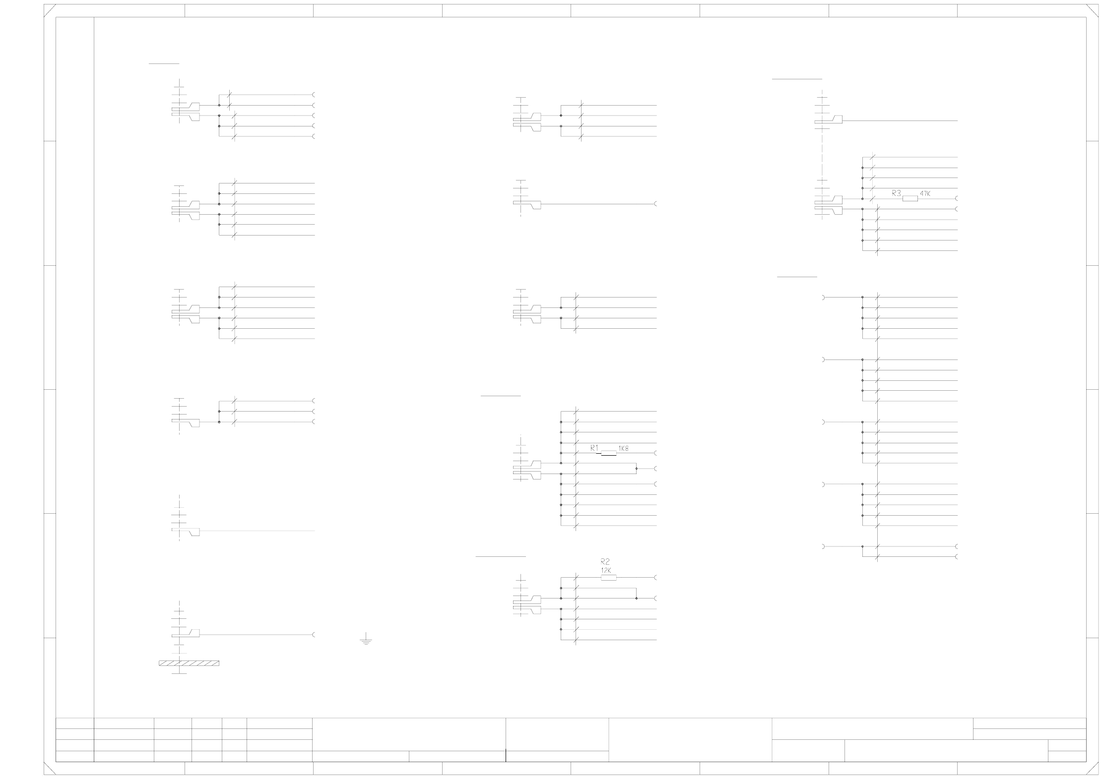
00335891-010201LD3 Servo unit without boards (Sh. 1 of 2)
X4vp/4
0 Volts
Plain washer
Plain washer
Plain washer
Plain washer
X9ym
Ballast
Plain washer
Retainer ring
Screw, M5X12
X7vf/2
M6 nut
+30 Volts
X1ym
Plain washer
Retainer ring
Screw, M5X12
wh (UL) / 1.0mm²
wh (UL) / 2.5mm²
X4vr/2
DP
2 45678
12345678
A
Screw, M5X12
X4vs/4
X4vw/4
X4vv/4
X4vo/4
X4vn/4
X4vr/4
X4vq/4
X4vu/4
X4vt/4
X4vm/4
M5 nut
B
C
D
E
X7vh/2
X7vd/2
X7vg/2
Screw, M5X12
X7vc/2
X10ym
X-P3
Y-P2
Y-P3
Plain washer
Retainer ring
wh (UL) / 2.5mm²
X-P2
wh (UL) / 2.5mm²
Plain washer
Retainer ring
Mutter M8
X6ym
N30
Plain washer
Retainer ring
Screw, M5X12
HEP
1
M6 nut
S-P2
X4vw/3
X4vu/3
DP-P3
DP-P2
Z-P3
Plain washer
X7vb/2
X7ve/2
Screw, M5X12
X7va/2
X8ym
X-P4
Y-P1
Y-P4
Plain washer
Retainer ring
wh (UL) / 2.5mm²
X-P1
X4vo/3
X60/1
X4vk/3
X3yn
gr (UL) / 0.75mm²
Retainer ring
M5 nut
wh / 0.34mm²
Anti-crash P1/P4
Retainer ring
Screw, M5X12
X4vk/4 S-P1
X4ym
Resistors R1-R3 (and their soldered joints) are insulated using heat-shrinkable sleeves !
DP-P1
Z-P4
Plain washer
Retainer ring
wh (UL) / 1.0mm²
Z-P1
X3ym
Power supply unit
TP 0V
Anti-crash P2/P3
wh (UL) / 1.5mm²
Power supply unit
Plain washer
From external power supply
X7ym
N200
X53/16
X7va/1
X-P3
Ballast
X-P2
X4vv/3
X52/32
DP-P1
Power supply unit
X2yn
X60/2
X4vq/3
X4vp/3
X4vt/3
3
Z-P4
P30
Z-P3
TP 30V
X-P1
Plain washer
Retainer ring
M6 nut
S-P4
S-P3
S-P2
DP-P4
DP-P3
DP-P2
X4vm/3
X4vn/3
X4vk/2
X6ve/2
X6va/2 X-P1
or / 0.34mm²
TP 6/100V
X2ym
S-P1
P6/100
Plain washer
Retainer ring
Z-P2
Y-P4
Y-P3
Z-P2
From external power supply
+15 Volts
+200 Volts
S-P4
DP-P4
X7vf/1
X7vh/1
X7vg/1
X7ve/1
X7vb/1
X7vd/1
X7vc/1
X-P4
bk (UL) / 1.5mm²
X4yn TP 200V
bk (UL) / 0.75mm²
X11ym
Plain washer
Retainer ring
M6 nut
X4vs/3
X6vc/2 X-P2
X5ym
S-P3
X60/4
1
Servo unit, without boards
#
Goller
21.01.1998
09.12.98
09.12.98
21.01.98
1.
2.
1.
Tek
Tek
Tek
2
00335891-010201LD3
X1yn
X53/22
X60/3
X52/16
X51/b31
X60/12
PL EA1 E2
X50/b31
X52/30
X60/11
=
SIEMENS AG
+
X-P3
+6/100 Volts
Anti-crash P2/P3
X52/12
Y-P2
Y-P1
X51/b30
X50/b30 Anti-crash P1/P4
X52/10
X4vw/2
X4vs/2
DP
Z
S
Y
X4vo/2
X6vh/2
X6vd/2
bk (UL) / 2.5mm²
Contact washer
Z
S
Y
X4vn/2
X6vg/2
Y
Lateral part
X4vr/3
Z-P1
X4vq/2
DP
Z
S
Y
X4vm/2
X6vf/2
X6vb/2 X-P4
X52/4
X4vt/2
X4vp/2
DP
Z
S
gnye (UL) / 2.5mm²
Plain washer
Retainer ring
M5 nut
X52/6
X4vu/2
X4vv/2
X52/8
FF
E
D
C
B
A
Weitergabe sowie Vervielfaeltigung dieser Unterlage, Ver-
wertung und Mitteilung ihres Inhalts nicht gestattet, soweit
nicht ausdruecklich zugestanden. Alle Rechte vorbehalten, ins-
besondere fuer den Fall der Patenterteilung oder GM-Eintragung. Bauteilangaben nur zur Information
Comunicado como segredo empresarial. Reservados todos os direitos.
Confie a titre de secret d'entreprise. Tous droits reserves.
Proprietary data , company confidential . All rights reserved.
Confiado como secrete industrial. Nos reservamos todos los derechos.
SMD-Placement System Siplace HS60
Product status
Doc. status
Function status
Status DateModified Name Stand. Orig. Replacement for Replaced by
Author
Date
Check.
Sheet
Sh.
3 - 3
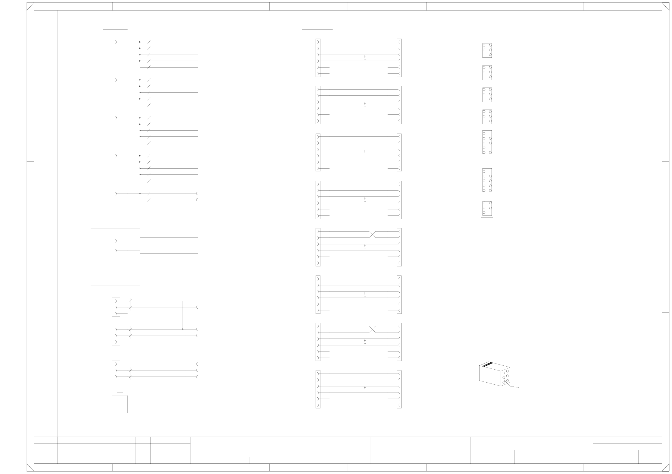
00335891-010201LD3 Servo unit without boards (Sh. 2 of 2)
=
SIEMENS AG
+
3
5
2
4
6
1
Enable
a21 = 0 Volts analog
Key Key
a28 = 0 Volts analog
8
123
Tacho-Y1
Enable
A
B
C
Weitergabe sowie Vervielfaeltigung dieser Unterlage, Ver-
wertung und Mitteilung ihres Inhalts nicht gestattet, soweit
nicht ausdruecklich zugestanden. Alle Rechte vorbehalten, ins-
besondere fuer den Fall der Patenterteilung oder GM-Eintragung. Bauteilangaben nur zur Information
Comunicado como segredo empresarial. Reservados todos os direitos.
Confie a titre de secret d'entreprise. Tous droits reserves.
Proprietary data , company confidential . All rights reserved.
Confiado como secrete industrial. Nos reservamos todos los derechos.
SMD-Placement System Siplace HS60
Product status
Doc. status
Function status
Status DateModified Name Stand. Orig. Replacement for Replaced by
Author
Date
Check.
Sheet
Sh.
Tacho-X4
Enable
Tacho-Y4
Enable
Tacho-X2
Enable
Tacho-Y2
Enable
Tacho-X3
Enable
Tacho-Y3
S
Z
DP
X4vp/1
Key Key
b28 = Distance sensor, analog
Ventilation OK
X60/9
P24
a26 = Distance sensor, digital
Key Key
Key
Key Key
Key
Key Key
b21 = Distance sensor analog
b27 = B2-prox. switch Y4 [Y3]
a19 = Distance sensor, digital
132 4567
Y
S
Z
DP
4 78
5
9
13
D
E
FF
Key
Key
Enable
Key
Key
Y
S
Z
DP
X4vs/1
X4vw/1
X52/24
bl / 0.34mm²
X-P1
X6va/1
X6ve/1
X4vk/1
Y
Y1 [Y2] - gantry
X4 [X3] - gantry
Y4 [Y3] - gantry
b
X51b7
X51a13
X51b13
b31 = 0 Volts
a31 = Crash signal
b32 = -15V
17
24
b17 = Ref. prox. switch X1 [X2]
b18 = B2-prox. switch X1 [X2]
Null
Key
Key
0.34mm²
X6vb/1
X6vf/1
X4vm/1
Y
S
Z
DP
X4vq/1
X4vu/1
X52/20
X-P2X6vc/1
X6vg/1
X4vn/1
X1ua/2
X1ua/1
X
X
X4vr/1
X4vv/1
X5va/3
C
B
A
X50a10
X50a9
X50b9
XX
X
XX
X
X50 [X51]
X1 [X2] - gantry
Gantry 1 [2]
Gantry 4 [3]
(Prox. switches)
(Prox. switches)
X=pinched off
1
30
X5vb/6
X5vc/2
X5vc/1
X5vc/4
a
a30 = Control On
b30 = +15V
X
X
X
65
b20 = B2-prox. switch Y1 [Y2]
b24 = Ref. prox. switch X4 [X3]
b25 = B2-prox. switch X4 [X3]
b26 = Ref. prox. switch Y4 [Y3]
X5vg/3
X5vg/6
X5vh/2
X5vh/1
X5vh/4
X5vh/3
X5vh/6
pk
vi
X60/6 Control On
bn
X1ua
bn
Crash signal P2/P3
X50a3
X50b3
X5va/2
X5va/1
X
E
D
X51a15
X51b15
X5vf/2
X5vf/6
X5vg/2
X5vg/1
X5vg/4
X51b1
X51a2
X51b2
X51a3
X51b3
X51a9
X51b9
X51a10
X51b10
X51a11
X51b11
X5vb/2
X5vb/1
X5vb/4
X5vb/3
X50/a32
X51/a30
X51/a31
X51/a32
X5vc/3
X
X
X5vd/1
X5vd/4
X5vd/3
X
X
X
X50a6
X50b6
X50a7
X50b7
0.34mm²
gn / 0.34mm²
0.5mm²
rd (UL)
bk (UL)
12
34
Viewed from
cable entry side
X50a1
X50b1
X50a2
X50b2
X50a5
X50b5
X52/22
X-P3
X5va/4
X51a14
X51b14
X6vd/1
X6vh/1
X4vo/1
X5vf/1
X5vf/4
X5vf/3
X50b10
X50a11
X50b11
X51a1
bl / 0.34mm²
Anticrash P1/P4X50/b32
X51/b32
X52/26
Anticrash P2/P3
-15 Volts
Ballast resistor
External
Ballast resistor
X53/10
X53/30
Anti-crash/fan
X50/a30
X50/a31
Tacho-X1
Anticrash
X60/8
X60/7
X60/5 Crash signal P1/P4
X60/10
X
X51a7
XX
X5ve/2
X5ve/1
X5ve/4
X5ve/3
X5ve/6
b19 = Ref. prox. switch Y1 [Y2]
X50a13
X50b13
X50a14
X50b14
X50a15
X50b15
X51a5
X51b5
X51a6
X51b6
X
X1ua/4
X5vc/6
X5vd/2
X5vd/6
2
Tek
Tek
Tek
1.
2.
1.
21.01.98
09.12.98
09.12.98
21.01.1998
Goller
#
Servo unit without boards
2
X
X4vt/1
X52/18
X-P4
X5va/6
00335891-010201LD3
PL EA1 E2
the numerical sequence of a Locking-clip connector
Make sure that ...
must be as viewed from the rear side of the casing.
Cable
3 - 4
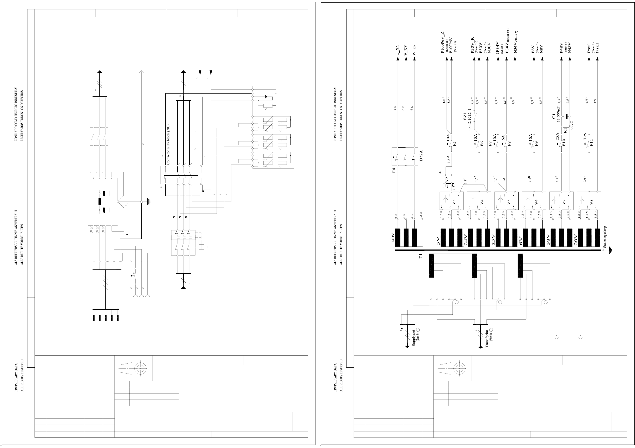
00336145-030201LD4 HS60 circuit diagram with option lifting table (dual conveyor) (Sh. 1 of 6)
00336145-030201LD4 HS60 circuit diagram with option lifting table (dual conveyor) (Sh. 2 of 6)
25
25
25
25
10
22
22
22
22
with option lifting table (dual conveyor)
HS60 circuit diagram
25.6.99
Technical aspects
ModifiedStat. NameDate Replacement for Replaced by
Massstab: Weight:Untol. dimens.
Check.
Stand.
Author
Date
Sheet
Sh.
0.75
0.75
1.5
1.5
1.5
0.75
0.75
1.5
1.5
1.5
1.5
1.5
1.5
So1
1234
D
C
B
A
E
A&D CD TDV Bremen
SIEMENS
Cramer
Willnecker
TEF3 Typ 4AV1301-4CT-1D
00336145-030201LD4
AutoCAD
6
1
(Main groundig point)
6 br
6 br
6 br
PE
V
St1
U
W
X1
V
U
W
PE
N
6 br
N
PE
F1
6
4A
1
0,75
2
1 2
A1(+)
4
5 6
A2(-)
4
11
12
11
21
14
13
22
21
31
24
23
32
31
34
33
4241 4443
Nsz1
Psz1
EST
25
25
22
22
1N4007
PE
Z1
43
1
2
5 6
6
SZ1
S1
6
HS1
HS1
U
V
MS1
1
3
2
4
6
W5 6
Sheet 1
4
43
0,75
4
K11
GPR
Grounding point of rack
Main power filter
Main switch
(Hat rail 1)
(Sheet 1)
Main contactor
Transfprim
(Sheet 2)
(Sheet 2)
Inrush-current limiter, transformer
To MGP
Protective motor switch
3-phase current
power connector
Grounding
socket
PCB handling
Z/D servo
Star servo
DC/DC converter
Comp. table
Comp. table
resistor
resistor
Make primary power lines
to transformer 100 mm longer.
Make a loop, if necessary
1234
D
C
B
A
E
SIEMENS
A&D CD TDV Bremen
TEF3
Willnecker
Cramer
00336145-030201LD4
Typ 4AV1301-4CT-1D
AutoCAD
2
6
with option lifting table (dual conveyor)
HS60 power supply
Discharge
Discharge
4V1
2N
4U1
3U1
3V1
3W1
2W1
2V1
2U1
1U6 204V
1V1 415V
1V3 400V
1U5 230V
1U4 380V
1U3 400V
1U1 415V
3
1
5
4
2
6
1
2
8W1
8V1
8U1
7U1
7V1
7W1
6U1
6V1
6W1
5U1
5V1
5W1
4W1
Sheet 2
1W6 204V
1V6 204V
1W4 380V
1V4 380V
1W1 415V
1W5 230V
1W3 400V
1V5 230V
1
2
1
2
1
1
1
2
2
2
Fit wires of board net on
jumpered terminals
2
29.6.99
Technical aspects
Stat. Modified NameDate Replacement for Replaced by
Untol. dimens. Scale: Weight:
Check.
Stand.
Date
Author
Sheet
Sh.
1
2
1
2
1
1
2