circuit of HS60.pdf - 第167页
5 - 35 0035942 4-010 101ND 4 961 board, conversi on boar d, tra nsportation cheek (Sh. 1 o f 2) 0035942 4-020 101ND 4 961 board, conversi on boar d, tra nsportation cheek, conn ecto r as sign ment ( Sh. 2 of 2 ) G32918 -…
5 - 34
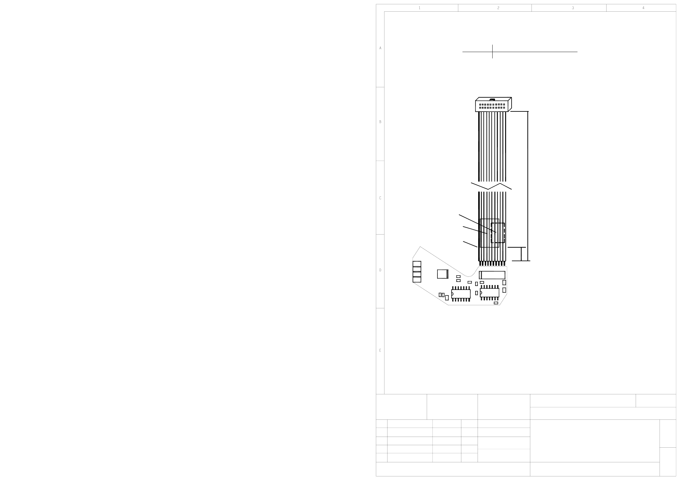
00359364-010101ND4 Adjustment unit 2 / reject circuit
Mounting diagram, component side
Adjustment drive 2
Reject circuit
00359364-010101ND4
1
1
SIEMENS AG
06.11.2001
06.11.200101
Stat. Modified Date Name
Date
Name
Sheet
Sh.
U2
R9
X4
X5
X3
X2
C4
C3
U3
R2
R1
B1, B2
A1
Pin 1
U1
C2
C6
X1
1
R5
R6
C5
10
R8R7
50.0mm
340.0mm
+5.0mm
-5.0mm
B1, B2:
A1:
X1
on the cable
On the back.
Label position:
AFO and WIP inspection labels.
50mm distance from cable end.
May be printed
readable, when X1 is on the left.
Identification label,
Cable, 05-1630-4
Assembly
X19 stepping motor boardoard 00344488
Connector
X1
readable, when X1 is on the right.
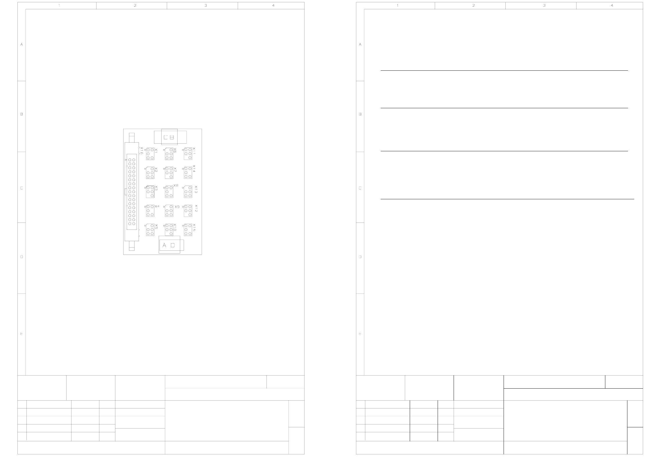
5 - 35
00359424-010101ND4 961 board, conversion board, transportation cheek (Sh. 1 of 2)
00359424-020101ND4 961 board, conversion board, transportation cheek,
connector assignment (Sh. 2 of 2)
G32918 - M0068 - U201 - * - 53
01
Stat. Modified Date
12.12.00
Name
KD
ATD TD E
SIEMENS AG
MCHN R/Tu
12.12.01
Dorfner
PC board
Date
Name
2-layer
00359424-010101ND4
Conversion board
PC board
Scale
1 : 1
Component layout, component side
Sheet
1+
961
Transportation cheek
Testing label (solder side)B
Identification labelA
Assembly designation 11x13
UL label (solder side)
C
D
G32918 - M0068 - U201 - * - 53
01
Stat. Modified Date
12.12.00
Name
KD
ATD TD E
SIEMENS AG
MCHN R/Tu
12.12.01
Dorfner
PC board
Date
Name
2-layer
00359424-010101ND4
Conversion board
PC board
Scale
1 : 1
Sheet
2 -
961
Transportation cheek
2
4
6
2
6
1
5
6
2
4
6
2
2
6
1
2
3
12
5
33
4
2
666
1
3
2
6
2
5
3
6
5
3
2
6
2
4
3
6
3
6
2
1
5
6
3
22
3
5
6
1, 2
3, 4
5, 6
7, 8
9, 10
11, 12
13, 14
15, 16
17, 18
19, 20
21, 22
23
24
25
26
27
28
29
30
31
32
33, 34
Connector X1 Connector X2 Connector X3 Connector X4
MOTOR 4-
MOTOR 4+
Key
Connector X5 Connector X6 Connector X7 Connector X8
Connector X9 Connector X10 Connector X11 Connector X12
Connector X13 Connector X14 Connector X15 Connector X16
MOTOR 3+
EA5
GND
EA7
EA8
EA9
EA6
MOTOR 4+
MOTOR 4-
MOTOR 5+
MOTOR 5-
MOTOR 3-
GND
EA0
EA2
EA3
EA4
EA1
MOTOR 1-
MOTOR 2+
MOTOR 2-
MOTOR 1+
EA6
+24V
GND
Key
Key
GND
EA2
+24V
MOTOR 3-
EA5
Key
GND
+24V
EA9
+24V
GND
Key
Key
GND
EA1
+24V
MOTOR 3+
Key
MOTOR 2-
EA4
Key
GND
+24V
EA8
+24V
GND
Key
+24V
GND
Key
EA0
MOTOR 2+
Key
MOTOR 1-
MOTOR 1+
MOTOR 5+
MOTOR 5-
Key
+24V
GND
EA7
Key
EA3
GND
+24V
Key
Key
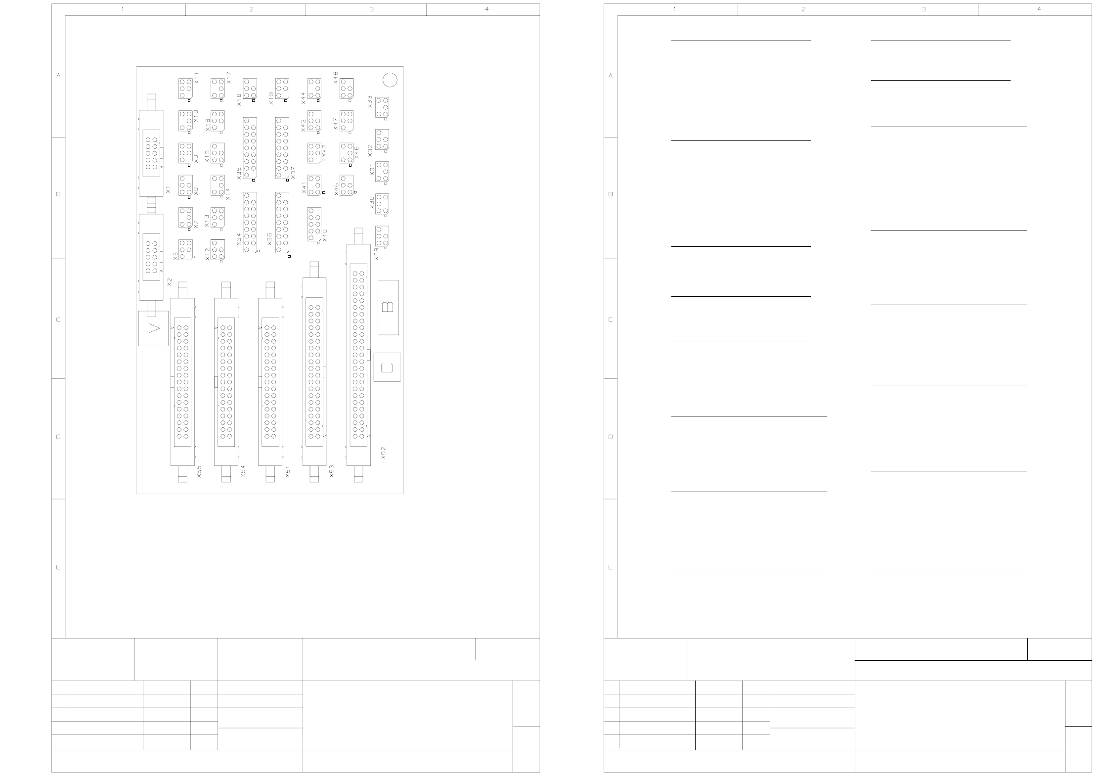
5 - 36
00359425-020101ND4 962 board, conversion board, conveyor 1 (Sh. 1 of 3)
00359425-020101ND4 962 board, conversion board, conveyor 1,
connector assignment (Sh. 2 of 3)
G32918 - M0069 - U021 - * - 17
01
Stat. Modified Date
12.12.00
Name
KD
ATD TD E
SIEMENS AG
MCHN R/Tu
12.12.00
Dorfner
PC board
Date
Name
2-layer
00359425-020101ND4
Conversion board
PC board
Scale
1 : 1
Component layout, component side
Sheet
1 +
962
Conveyor 1
KD04.04.0102
KD10.07.0104
Identification label 11x13A
Inspection labelB
Assembly designationC
G32918 - M0069 - U021 - * - 17
01
Stat. Modified Date
12.12.00
Name
KD
ATD TD E
SIEMENS AG
MCHN R/Tu
12.12.00
Dorfner
PC board
Date
Name
2-layer
00359425-020101ND4
Conversion board
PC board
Scale
1 : 1
Sheet
2 +
962
Conveyor 1
KD04.04.0102
KD10.07.0104
1
2
3
4
5
6
10
+24V
GND
5
6
10
2
3
4
1 +24V
GND
Option
1
2
3, 4
5, 6
Key
--> X52.48
+24V
GND
2
3
4
5, 6
--> X52.32
+24V
Key
GND
2
3, 4
5
6
--> X52.33
+24V
Key
GND
--> X52.172
GND
+24V3, 4
5, 6
Key1
1
2
3, 4, 5
6
7, 8, 10
9
Key
SM_A+
SM_A-
SM_B+
SM_B-
Key
2
3
4
5, 6
--> X52.43
+24V
Key
GND
1
2
3, 4
5, 6
Key
--> X52.19
+24V
GND
6
5
3, 4 +24V
GND
Key
--> X52.212
2
3
4
5,6
--> X52.23
+24 V
Key
GND
2
3, 4
5
6
--> X52.44
+24V
Key
GND
Connector X19/Endschalter
width adjustment, 1. side panel
Connector X18/stopper, PCB detection
Connector X17/stopper, cylinder switch
Connector X11/stopper, valve
Connector X12/X13/X14/X15/X16
Connector X6/X7/X8/X9/X10
Connector X2
Connector X1
Lifting table 2, valve 'down'
Lifting table 2, valve 'up'
Lifting table 2, limit switch
Lifting table 2, track A
Lifting table 2, track B
Spare
Lifting table 1, valve 'down'
Lifting table 1, valve 'up'
Lifting table 1, limit switch
Lifting table 1, track B
Lifting table 1, track A
Adjustment drive 2, valve
Limit switch, right spindle
Connector X45/width adjustment
Connector X44/width adjustment
Adjustment drive 1, prox.sw. f. cheek
Adjustment drive 1, cylinder switch
Connector X40/ width adjustment
Connector X29/X30/X31/X32/X33
Adjustment drive 1, valve
Connector X43/width adjustment
Connector X42/width adjustment
Connector X41/width adjustment
Step motor
Options
Connector X34/X35/X36/X37
Spare