circuit of HS60.pdf - 第46页
2 - 2 NH02 Emerg enc y-st op lo op, emer gen cy-s top butt ons , pro tect ive swi tch es (Sh. 2 o f 2) S826 b (S1) (S1) (S1) S826 b (S1) (S1) (S3) S826 b (S1) (S1) (S3) 1 3 2 4 The wire colors in the drawing correspond t…
2 - 1
2 Detailed Circuit Diagrams
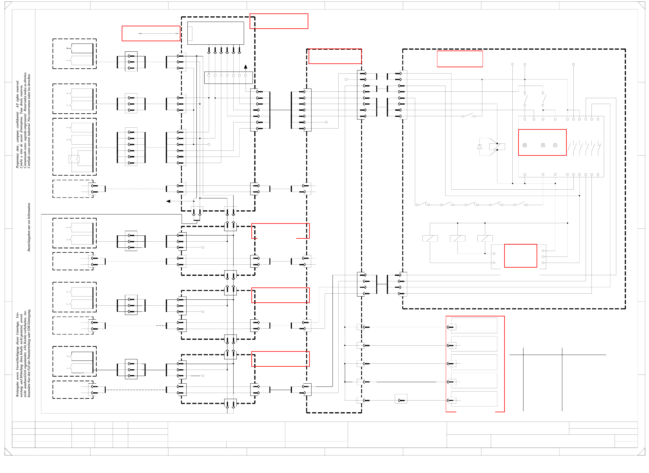
NH01 Emerg.-stop loop, Start buttons, Stop buttons, keyswitch (Sh. 1 of 2)
S_StartButton
16c
17c
S_StopButton
20a
18c
Emerg.Stop
S_KeySwitch
21c
22c
23c
Ctrl_On
S_Ready
Control On
X400:
DEMATIC
SIEMENS
Function status
Product status
Doc. status
SMD Placement System SIPLACE HS60
servo
supply
Sheet
Sh.
NH01.DWGCAD file:
Orig. Repl. f. Replaced by
Date
Author
Check.
Stand.NameDateModifiedStatus
Di1
bk
S2
S2
S1
S2
S1
S4
S3
rd+gn (W2)
bk (W1)
S2
W1
W2
W1
55
bl
77
ye
77
Warning !
If cables are used corr. to the DIN 47100 color code, please use the table below!
The wire colors in the drawing correspond to the Belden color code.
4
12
8
11
10
9
6
7
5
2
3
1
Wire
Greengn
Tanlibn
Pink
Violet
Orange
Brown
Yellowye
pk
gy
vi
Gray
bl
or
bn
Blue
White
Black
Belden color code
wh
rd
bk
Red
Yellowye
rd+bl
rd
gypk
vi
bk
pk
bl
gy
red+blue
Red
Gray+Pink
Violet
Black
Blue
Pink
Gray
DIN 47100 color code
bn
gn
wh
Green
Brown
White
START buttons STOP buttons
Keyswitch
SSK54
SSK53
SSK43
SSK44
SSK53
SSK54
SSK43
SSK44
N. u.
N. u.
N. u.
N. u.
S1
S1
StartStartStart
PCB output, righth. side
Start Stop Start
Pneumatic panel PCB input, lefth. side
bk+wh
2P34V
P34V
16c
18c
23c
20a
21c
22c
X400
Sector 4
To sheet 2
X400:20b
X2
X1
X11
X6
X7
X8
dm:1
dm:1
dm:1
dm:1
dm:2
5
Start
3434
Stop
34 3434
3
bl
bk+wh
vi+gy
2
ye
7
1
rd
gn
rd
bk+wh
1
2
1
bk+wh
55
1
bl
bl
5
1
4
wh
wh
SD EA1 E2
5
bk+wh
55
bl
5
5
1
bl
5
rd
gn
P24V
+24V
wh
8
9
bk
7
bk+wh
343434
bl
1
2
bl (W1)
5
3
1
rd (W1)
wh+bk+bn (W1)
6
4
5
bl (W1)
rd+gn (W2)
wh+bk (W2)
rd (W1)
gn (W1)gn (W1)
rd+gn (W2)
bk+wh (W2)
bk+wh+bn (W1)
2
5
00335307
00335271
X84
00335306
00335275
bl
bk+wh
X85
00335307
bk
rd
bl
00336154
Power supply
W2
wh
rd
bk
rd
wh
rd
125kbps
X18dm
CAN bus
1
2
F
2P 34V
P 24V
NC_TapeCutter
Emerg. stop
S_StartButton
Ctrl_On
S_Ready
Control on
PCC
Channel2Channel1Power
00336145
Inrush current
infeed
limiter,
X12
X9do X2ah
infeed
Tape cutter (ah)00335235
X10do X2bh
infeed
Tape cutter (bh)00335236
X11do X2ch
72
7168
61
bk
Zero
SZ23
K232
4
K14
SZ2
43
9
P34V
+24V
5
17c
SZ23
K234
21
73
66L- X4 X6
5343332313 65
1
2
2
1
1
2
1
2
1
22
00335248
X6cf
X6bf
X6af
Distributor, sector 2 (bf)
Distributor, sector 1 (af)
wh
X1af
Distributor, sector 3 (cf)
X3cf
X7cf
00335264
X12do X2dh
infeed
Tape cutter (dh)00335238
X13do X90
main valve
Tape cutter,
00335239
Main distributor (do)
00335245
X27do
00335246
X28do
00335247
X29do
3
X3bf
X7bf
00335260
X4af
00335262
bl
bk+wh
X82
00335306
F
X3af
X7af
8
A
2
D
3
C
B
A
5
B
rd
+24V
4
5wh
bk
A1A2
P34V
wh
bk
wh
4
1
7
bk
1 bk+wh
bk4
5
wh
bk
2
+24V
4
5
5
1
rd
bk
1
4
Tape cutter (ch)00335237
4
4
3
3
00335244
X26do
X25do
00335223
X13
00335221
1
rd
bk+wh
X87
00335285
gn
rd
X4cf
X10df
X4df
X11df
41
E
5
4
X31do
X6df X3df
Distributor, sector 4 (df)
X24do
00335268
X7df
X12df
00329698
CAN I/O module 1
00335281
1
C
D
E
678
76
Side of power supply
X86
gn (W1)
rd (W1)
bk+wh+or (W1)
bk+wh (W2)
rd+gn (W2)
bl (W1)
wh+bk (W2)
00335283
gn (W1)
wh (W1)
rd (W1)
bl (W1)
bn (W1)
X4bf
00335284
gn
1.
1.
1.
27.01.03
27.01.03
27.01.03
27.01.2003
Hi
Emergency-stop loop
NH01-010101LD3
1
Key
switch
W1
W2
W3
00335259
00336152
00336181
00336182
00336153
3
P24V
SZ4
4
3
2
Hi
Hi
Hi
6
bk
rd+gn
3
5
2
bk+wh
bl
5
6
wh
rd
bn
8
14 24
or+ye
5
6
9
4
5
bk
wh 5
rd
gn
4
or+ye
wh2
6
5
3
4
bl
bn
8
2
3
6
3
2
4
3
X5X3X1L+
4
34 44 54
1
vi+gy
2
8
gn
5
4
9
SZ3
21
SZ4
65
SZ4
wh
SZ2
K24
21
K34
bk 1
1
1
1bk
bk 1
1
1
1bk
SZ3
A1A2
SZ2
A1A2
1
SZ23
A1A2
rd
bk+wh
SZ4
2
1
2
1
gn
3
3
6
5
1
7
3
4
5
3
wh
2
1
bk
rd
bk
gn
rd
3
bk+wh
rd+gn
5
4
6
1
4
=
+
W2
W2
W2
W2
Option
X1bf
Option
X1cf
Option,
external emerg.-
stop loop
Option
X1df
Option
ILS
bk
X96
00337809
00335266
X83
7
ye
ye
6or
6or
6or
6 orgn
rd
gn
1
bk+wh
6
5
or
bl
gn
rd
1
5
bk+wh
bl
6or
gn
bk
34
S2
Stop
external emerg.-
stop loop
Option,
PCB output, lefth. sidePCB input, righth. side
external emerg.-
stop loop
Option,
gn
Stop
S3
3443
Stop
S2
bk
gn
external emerg.-
stop loop
Option,
gn or6 or 6
S3
Stop
3 4
gn
wh
wh
7
bl
ye
bk+wh
bk+wh
bk+wh
X400:17b
X400:10a
dm:1
S_StartButton
Emerg. stop
Ctrl_On
S_Ready
Control on
2P 34V
See page 3-9
See page 3-13
See page 3-5
See page 3-19
See page 3-18
See page 3-7
See page 3-6
See page 5-7
See page 2-48
See page 3-6
2 - 2
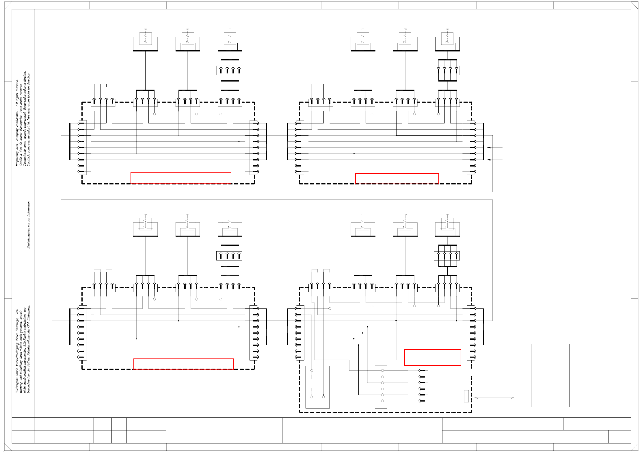
NH02 Emergency-stop loop, emergency-stop buttons,
protective switches (Sh. 2 of 2)
S826 b (S1) (S1) (S1)S826 b (S1) (S1) (S3)
S826 b (S1) (S1) (S3)
1
3
2
4
The wire colors in the drawing correspond to the Belden color code.
If cables are used corr. to the DIN 47100 color code, please use the table below!
Warning !
4
12
8
10
11
9
6
7
5
2
3
1
Wire
ye Yellowgn Green
libn Tan rd+bl
Yellow
Brown
Orange
Violet
ye
gy
pk
vi
Gray
Pink
bl
or
bn
Blue
rd
vi
gypk
bk
pk
bl
gy
Red+Blue
Red
Black
Violet
Gray+Pink
Gray
Pink
Blue
DIN 47100 color codeBelden color code
Black
Whitewh
rd
bk
Red
bn
gn
wh White
Brown
Green
Protective switches
Emergency-stop buttons
rd
or
bn
gn
bk+wh bk+wh
gn
bn
or
rd
bk+wh
gn
bn
or
rd
X300:7b
+24V
X300:7c X300:7a
+24V
X100:7a
+24V
X100:7b
+24V
X100:7c
+24V
X200:7c
+24V
X200:7b
+24V
X200:7a
+24V
+24V
X400:11c X400:9b
+24V
X400:9a
+24V
X400:9c
+24V
S_Comp. flap,
S_Comp. table,
S_Emerg. stop b.,
S_Cover,
X400
R1
X400
+24V
30a 30c
6-pole12-pole
12-pole 6-pole 12-pole
12-pole 6-pole
6-pole
Function status
Product status
Doc. status
SMD Placement System SIPLACE HS60
NH02-010101LD3
Replaced by
Sheet
Sh.
NH02.DWG
SD EA1 E2
CAD file:
Status Modified Date Name Stand.
Check.
Author
Date
Orig. Repl. f.
S826 b (S1) (S1) (S1)
1
3
2
4
=
+
2
4
3
1
4
00336152
0033618100336182
00336153
Comp-ProtectiveFlap2
00337052
ye
gn
bn
wh
14
22
00335263
ye
00337052
ye
gn
bn
wh
Comp-ProtectiveFlap1
00337052
ye
gn
bn
wh
gn
bn
wh
ye
gn
bn
wh
ye
gn
bn
wh
ye
1
3
4
2
bn
wh
ye
2
wh
rd
gn
bk
Emergency-stop, input, righth. s.
00335306-W2
1
6-pole
6-pole6-pole
6-pole
27.01.03
27.01.03
27.01.03
27.01.2003
SIEMENS
DEMATIC
3
2
4
bk
wh
rd
gn
Cover, input
00335307-W1
13
21
14
22
ye
wh
bn
gn
13
21
00337737
0033773700337737
Emerg.-stop
(loop end)
wh
bn
gn
13
21
14
22
00335263
ye
wh
bn
gn
13
21
14
22
00335263
ye
wh
bn
gn
13
21
14
22
3
1
D
C
1
gn
3
1
4
2
bn
wh
ye
gn
3
1
4
2
bn
wh
ye
gn
3
1
4
2
bn
wh
ye
gn
Comp-ProtectiveFlap4
00337737
gn
wh
X82
00335262
00329698
CAN I/O module
bk+wh
rd
gn
bn
or
00335268
Status illustrated in this drawing:
covers closed,
emergency-stop buttons not pressed.
S_Cover
X17dm
A2 (dm)
X4dm:1
X9dm:1
X5dm:1
X3dm:1
125kbps
CAN bus
wh
rd
gn
X84
S_Emerg.StopB
S_Comp.Table
S_Comp. flap
rd
gn
rd
bk
Cover, output
D
3
C
B
A
5
B
32
F
41
E
5
4
F
Distributor, sector 4 (df)
rd
bkbn
rd
gn
bk+wh
4
1
3
bk+wh
8
A
2
gn
bk+wh
gn
rd
bn
Prot. cover 4
wh
rd
bk
X85
00335275
bn
rd
gn
bk+wh
gn
Prot. cover 1
wh
wh
X6df
X4dfX5dfX25df
00335266
X83
ye
00335306-W2
wh
Prot. cover 2
ye
gn
bk
bk
wh
bn
Emerg.-stop, output, righth. s.
bn
00335271
wh
gn
rd
bk
bk+wh
gn
rd
bn
gn
00335263
2
00335260
13
21
00335307-W1
Distributor, sector 2 (bf)
X3cf
X1cf X25cf X5cf X4cf
X6cf
Distributor, sector 3 (cf)
Comp-ProtectiveFlap3 Prot. cover 3
00337052
E
678
76
gn
bn
or
00335264
X3bf
gn
X1df
X3df
00335259
or
bn
gn
rd
bk+wh
or
bn
bk+wh
rd
X25afX1af
Distributor, sector 1 (af)
X6af
X4afX5af
X3af
22
14
1.
1.
1.
Hi
Hi
Hi
2
X6bf
X4bfX5bfX25bfX1bf
rd
gn
bn
or
bk+wh
rd 2
2
Emergency-stop loop
Hi
bn
3K3
4
4
1
2
4
1
bk+wh
rd
15a,c
14a,c
gn
bn
6
20b
4
1
13a,c
24a,b,c
6
2
3
4
3
6
2
1
4
3
3
2
1
2
4
1
rd
bk+wh
1
3
gn
A5
2
4
A6
A3
1
3
A4
3
6
4
1
4
3
2
+24V
3
4
3
6
2
1
4
1
3
bn
bk+wh
rd
1
gn
2
6
4
A5
3
6
4
2
2
3
1
2
1
1
3
2
4
A6
A3
A5
gn
3
A4
1
4
2
6
3
1
3
2
2
4
4
1
3
A5
2
A4
A6
A3
4
1
3
bk+wh
rd
2
bn
2
4
A4
3
1
A3
A6
7
8
9
8
9
7
5bl 5bl
yeye
N. u.
N. u.
N. u.
N. u.
See sheet 1
See sheet 1
bl 5 5bl
ye
N. u.
N. u.
7
8
9
7
8
N. u.
N. u.
ye
bl
55bl
8
9
7
N. u.
N. u.
ye
8
9
7
N. u.
N. u.
ye
5
bl
5bl
N. u.
N. u.
ye
9
8
7
8
9
7
N. u.
N. u.
ye
16a,c
17a,b,c
X8dm:1
X7dm:1
S_StartButton
S_StopButton
S_StopButton
S_StartButton
See page 3-19
See page 3-18
See page 3-7
See page 3-9
2 - 3
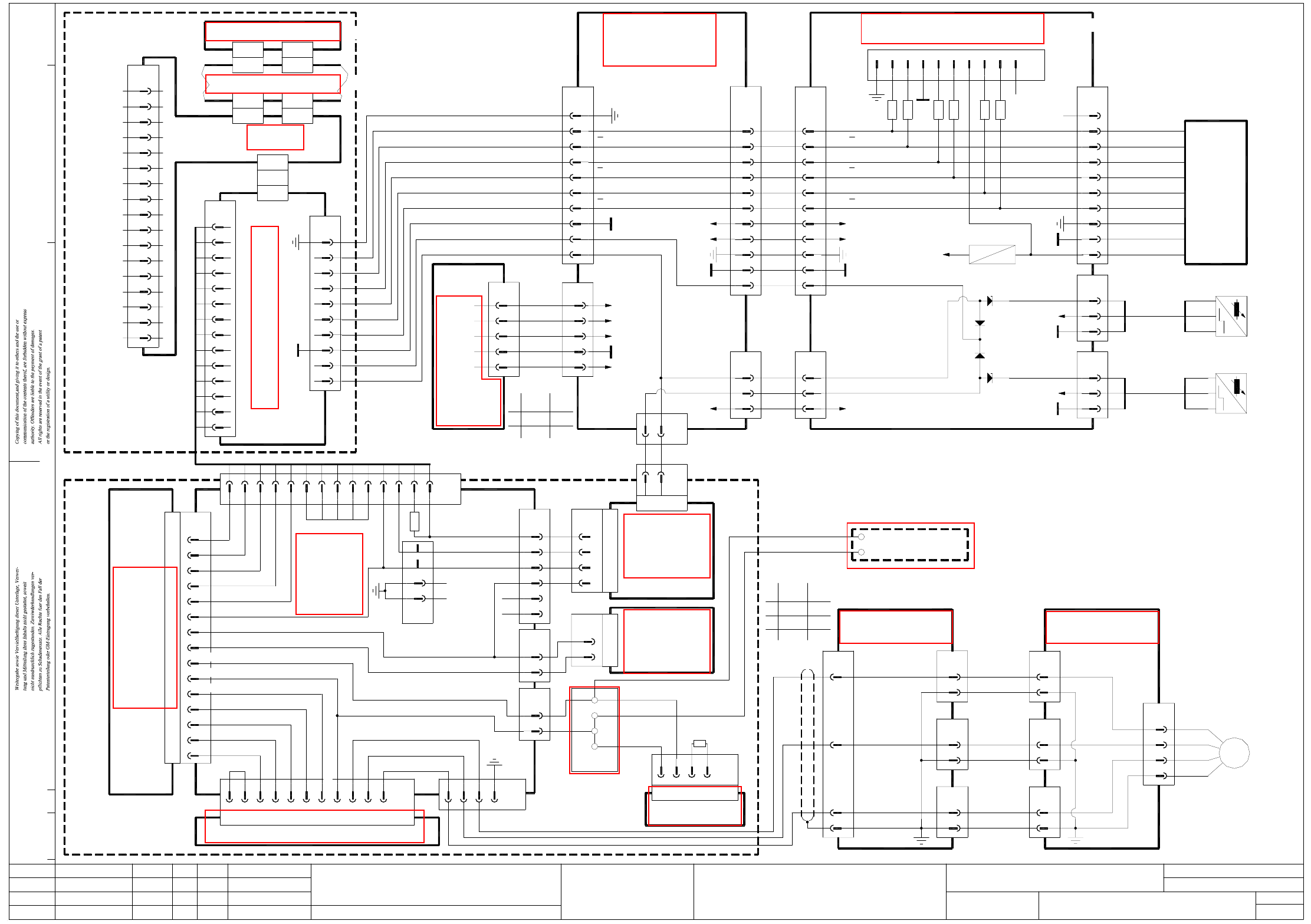
X01 X axis, gantry 1, SIPLACE HS-60
00335139-xx
(Cable)
8
9
27
26 Track N
Track N27
26
X2ac
00335109-xx
6
5
2
3
29
30
33
32
X2aa
(Cable)
Track B
Track B29
30
Track A
Track A
33
32
X24aa
10,11
12
13
GND
A
A
B
B
N
N
2525
+5V
+15V
1,341,34
31
GND
31
GND
X31aa
1
distributor
(do)
5
+5V
X2do
2
3
4
X15aa
1
-15V
00335413-xx (aa)
Gantry distribution board
Reference point
end position
X axis limit switch
Servo unit HS60
00334810-xx
X50
b17
X1wy
gantry 1/4
A30 (wy)
00335121-xx
(cable)
b183
(cable)
00335228-xx
2828
+5V
2424
wh
+15V
+24V
(W1)
(W1)
(W2)
(W1)
(W2)
00336154-xx
+15V
6
wh
00343441-xx
+5V
+24V
00335169-xx
X17ac
5
1
3
bl
bn
bk
bl
bn
bk
-
+
A1
End pos. prox.
switch B2
23 23
(Cable)
00335111-xx
reference point
X axis
End pos. proximity switch B1
X axis limit switch
End pos. proximity switch B2
Gantry head distribution board HS60 gantry 1
00344487-xx (ac)
A1 (ya), 00344204-xx
N.C.
Crash
X1wy
X50
b1
a1
00335892-xx
Anti-crash board
1,27,34
2,3,4,5,6,7,8
X7aa X2ab
00335113-xx
(cable)
XV3
00335112-xx
2,3,4,5,6,7,8
X6aa
(cable)
1,9-27,34
X3ab
XU
1*)
3*)
2*)
47100
Belden
wh
2*)
1*) bk
DIN
bn
wh
3*)
gnrd
V3
V5
V2
V4
00344207-xx
Cable color coding
Cable color coding
1
3
2
4
5
8
7
6
10
9
X24ac
key
6x470 10key
GND
GNDGND
Sh.
Sh.
Doc. status
Product status
Function status
01. Hi
Hi01.
Hi01.
Status Modified Date Name Stand.
Check.
Author
Date
Orig./Repl.f/Replaced by
CAD file:
X01-010101LD3
Mat. no.:
00336145-xx
Power supply
P200V
N200V
wh
bk
bl
or
wh
bk
27.01.03
27.01.03
27.01.03
27.01.2003
SIEMENS
DEMATIC
X4sa
XB7sy
X2sd
XC1sy
X4aa
24
X4ac
24
bl5 bl -
X16ac
1
3
00335170-xx
bn
bk bk
bn
+
A1
End pos. prox.
switch B1
+24V
00335413-xx
HS60 gantry distributor
gantry 1
X18aa
1
(aa)
X8aa
00335114-xx
2
3
00335414-xx
X/Y distributor, HS60
(cable)
X1ab
(ab)
gantry 1
1
X5ab
2,3,4,5,6,7,8
1,27,34
00343900-xx
Motor
or (U)
bk (V)
rd (W)
4 gnye
00333146-xx
(cable)
A33 (va)
HS60 gantry 1
bk
rd
X2tk
Machine controller M54 A1 (sa)
TBS 200 / 10X
X1ya
X-axis servo amplifier
4
00334808-xx
Control unit HS60
Cable 00335122-xx
nom. values
X axis
109
Axis rear panel, gantry 1 A31 (tk)
X axis
9
12
10
3
Crash
5
1
8
14
12
13
10
11
12
13
11
Servo unit
backplane
13
14
7
6
2
X3va
00335127-xx
(Cable)
XA1sy
X1tk
7
8
5
6
3
4
1
2
8
9
5
6
2
3
XA5sy
X1sd
A4 (sd)
Comb. backplane A39 (sy)
Axis board 1
XC1sy
X7tk
X2sd
X axis,
axis tracks
X1sa
GND
X5va
1
2
M
XW
5
3
2
incremental shaft encoder
X15ac
9
1
7
4
8
bk
rd
whgn
gy
bn
ye
pk
gn
b23
a24
6
5
key
Tacho_P
Tacho_N
1K
N.C.
X4va
3
1
2
4
N.C.
key
X1va
8/d
14/d
12/z
12/d
4/d
4/z
10/d
16/d
30/d,b,z
6/d
6/z
32/d,b,z
26,28/d,b,z
22,24/d,b,z
18,20/d,b,z
INOM_U
INOM_W
Servo Enable
I²t
00333635-xx
(gantry 1)
AC 12,5
Servo
Ready
6/d,b,z
8/d,b,z
2/z
2/b
30/d,b,z
32/d,b,z
26,28/d,b,z
20/d,b,z
24/d,b,z
18/d,b,z
22/d,b,z
X2va
N.C.
Brake_P
Brake_N
Phase_U
Phase_W
Phase_V
X1wa
X01.DWG
Stromlaufplan/Circuit diagram
SD EA
Hi
SMD Placement System SIPLACE HS60
1
1
X axis, gantry 1
SIPLACE HS60
Dynamic brake, A9 (wa), 00344206-xx
X8va
1
4
2
3
Motor_W
Motor_U
Motor_V
d22
d30
z16
d10
X53
X1vz
Ballast Card, A29 (vz)
00335115-xx (cable)
1
2
X7va
Potential
X9 ym
X8 ym
X7 ym
X11 ym
GND
0/200V
1
2
X6va
+15V
-15V
X52
4
18
X1vy
distributor
Power supply
A32 (vy)
card +/-15V
00302841-xx
3.5
00335224-xx (cable)
00335225-xx (cable)
1*)
2*)
Belden DIN
47100
1*)
2*)
bk wh
bnwh
2
4
bk
XW
XV
XU
X axis
3~
signal
1
2
3
4
5
15V
5V
+15V
proximity switch 1
1,4,7
1,4,7
X-axis
34
12
20
9
10
11
7
8
5
6
3
4
X3sd
2
1
35
36
37
AGND
V NOM
I NOM
END SIGNAL
COUNT A
COUNT B
INDEX
TRIG
RxD
CAN_L
CAN_H
VREG
TxD
GND
VCC
+15V
-15V
HS60 main
X101/12a
X101/15a
X101/3a
X102/1
X101/18a
13 13
+24V
+24V
See page 1-25
See page 1-25
See page 4-4
See page 3-13
See page 5-14
See page 5-27
See page 1-25
See page 1-26
See page 3-3
See page 5-14
>
See page 5-15
See page 5-13
See page 3-6
See page 3-2
See page 4-4
See page 3-2
See page 4-4