1OM-1603-006_w.pdf - 第149页
1OM-1603 3-24 2. Pattern Program Change : Chap.3 1012-005 2.3.3 Setups for PCB Support Pins and Conveyor Width If the conveyor width is not correctly set, the PCBs cannot be transferred. Note Before starting the setup wo…
1OM-1603
3-23
2. Pattern Program Change : Chap.3
1108-006
2.3.2 Selection of Operation Mode
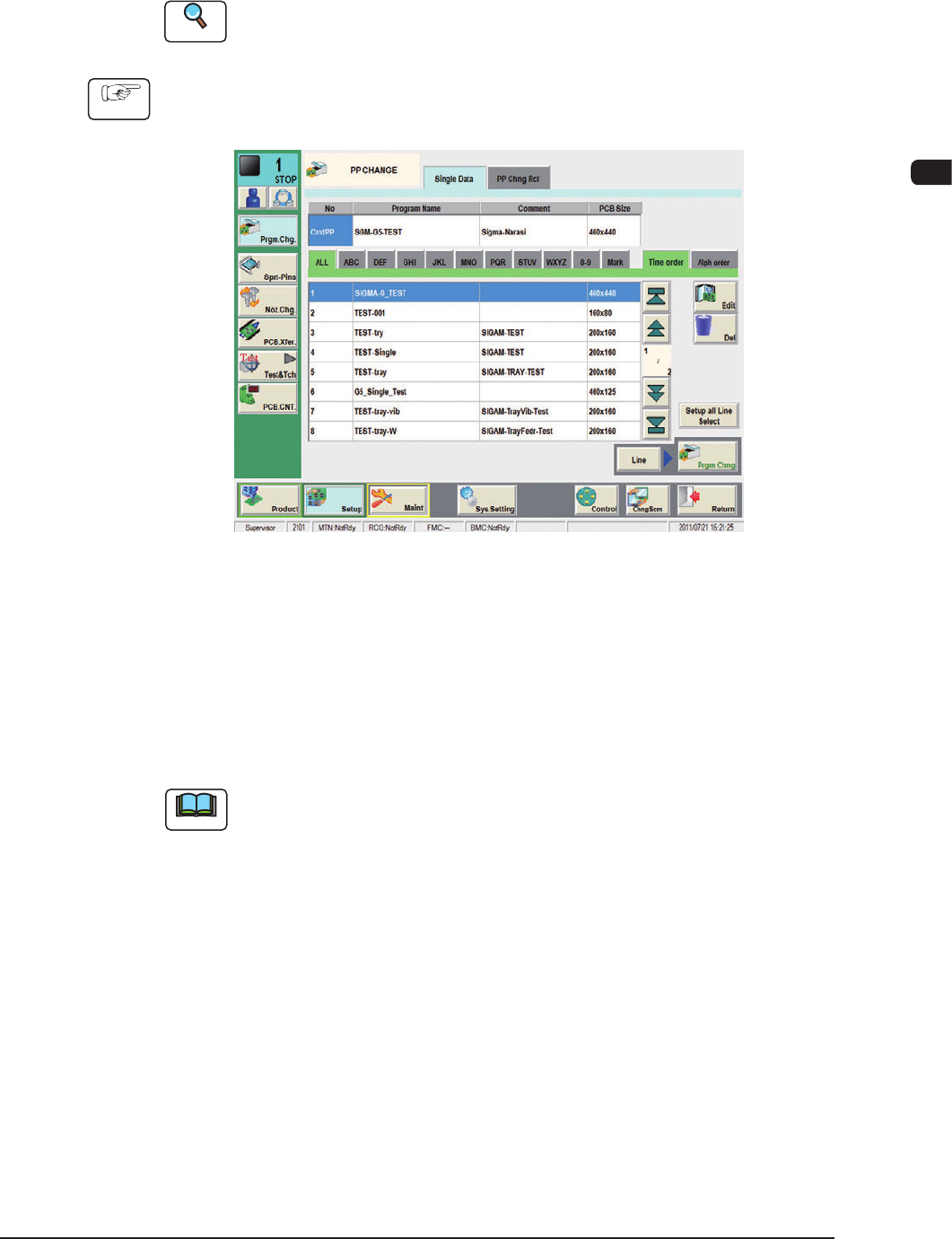
Using this window, the pattern program is changed.
Perform the support pin stock area editing before the pattern program change.
Reference
Refer to "Chapter 6: Product Change Menu" in Volume 2, for the details of the
stock area editing.
Procedure
(1) Press the [Setup] button on the common menu bar.
(The "PP CHANGE" window appears.)
F1C15
(2) Select the program name to be specied as a current one (production model).
(The corresponding pattern program will be selected and the line turns blue.)
(3) Press the [Prgm. Chng] button.
Within 10 seconds, press the [START] button on the operation panel.
(The current pattern program will be changed to the selected one.)
Note
(a) If an error is found in the pattern program, the program change operation is
not executed.
In this case, correct the pattern program and perform the program change
operation again.
(b) When the conveyor width change, support pin change and nozzle change
are performed at the same time, press the [Setup all Line Select] button and
set each of them as required.
(c) When the pattern program change is performed in the entire line, press the
[Line] button and them press the [Prgm Chng] button.
1OM-1603
3-24
2. Pattern Program Change : Chap.3
1012-005
2.3.3 Setups for PCB Support Pins and Conveyor Width
If the conveyor width is not correctly set, the PCBs cannot be transferred.
Note
Before starting the setup work, compare the status of PCBs (size, thickness,
existence of components placed previously on the back of PCB, etc.) to be
handled in the previous pattern program (the production model before the
program change operation) with that of PCBs to be handled after the program
change operation. After conrming the difference, determine whether or not the
conveyor width and PCB support pins should be set up.
Reference
Refer to "4. Sprt-Pins window" in Chapter 6, Volume 2 for the details.
2.3.4 Preparation for Vacuum Nozzles
Set the vacuum nozzles registered in the placement head / nozzle data of the
pattern program (for the production model).
Note
(a) When the total number of vacuum nozzles exceeds "15" before or after a
program change operation, perform the "Nozzle Reset" operation and then
the "Nozzle Change (Attachment)" operation.
(b) The original nozzle stocker addresses (from which the vacuum nozzles are
attached) are stored in memory of the machine. Therefore, each vacuum
nozzle is stored back in the original stocker address.
(c) When the support pin automatic setup is to be performed, set the nozzle
(PK01).
Notice
•
Be sure to attach the vacuum nozzles correctly in place.
When a vacuum nozzle is attached incorrectly (not to the place
speciedintheplacementhead/nozzledata),itmaycause
undesirable interference.
•
Do not put any foreign object in the nozzle stocker section.
Otherwise, the machine will break down.
NOTICE
Do not bring any magnetized object such as a
magnet close to the vacuum nozzles.
Otherwise, an error may occur during component picks
and placement.
1OM-1603
3-25
2. Pattern Program Change : Chap.3
•
Procedure of Vacuum Nozzles Replacement
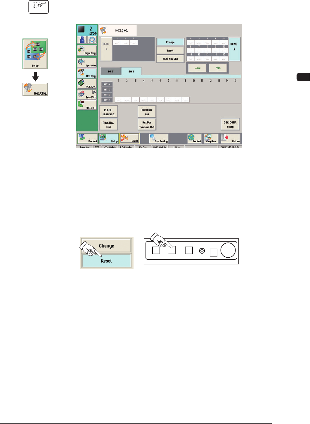
Procedure
(1) Press the [Noz Chg] button in the submenu on the [Setup] window.
(The "NOZ CHG." window will be opened).
F1C16
(2) Press the [Reset] button.
(3) Press the [MOVE] button and then, within 10 seconds, press the [START]
button on the operation panel.
(The vacuum nozzle on the placement head will be housed in the nozzle
stocker).
F1C17
Graphic
Development
1012-005