1OM-1603-006_w.pdf - 第97页
1OM-1603 1-40 4. Surface Mounting Mechanism : Chap.1 1012-004 Recognition Correction (Angular Correction) The picked component is adjusted to the angle (placement direction) of placement specied in the pattern program b…
1OM-1603
1-39
4. Surface Mounting Mechanism : Chap.1
1007-004
4.6 Component Recognition
Each head is also provided with a line sensor. The line sensor is used to detect a
component to be picked up and a vertical component. It is also used to measure
the component thickness.
The image of the component picked up by the vacuum nozzle is captured by the
component recognition camera for the inspection.
The back and front lighting recognition systems are adopted for component
recognition with the component recognition camera. Either one of the systems is
selected automatically according to the lighting mode specied in the component
library data.
Component Recognition Process
The following three operations are performed in the component recognition
system.
•
Component Detection
All components are regarded as object components for the detection.
•
Component Inspection
Various inspections are made according to the component library data.
•
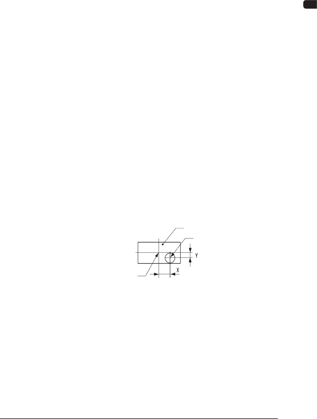
Measurement of Component's Positional and Angular Deviations
Measured are the positional deviations (X, Y) and the angular deviation (
q
)
between the centers of the component recognition camera and the center of
component.
Component
Center of Component
Vacuum Nozzle
State of Component Picked Up by Vacuum Nozzle F1A34
1OM-1603
1-40
4. Surface Mounting Mechanism : Chap.1
1012-004
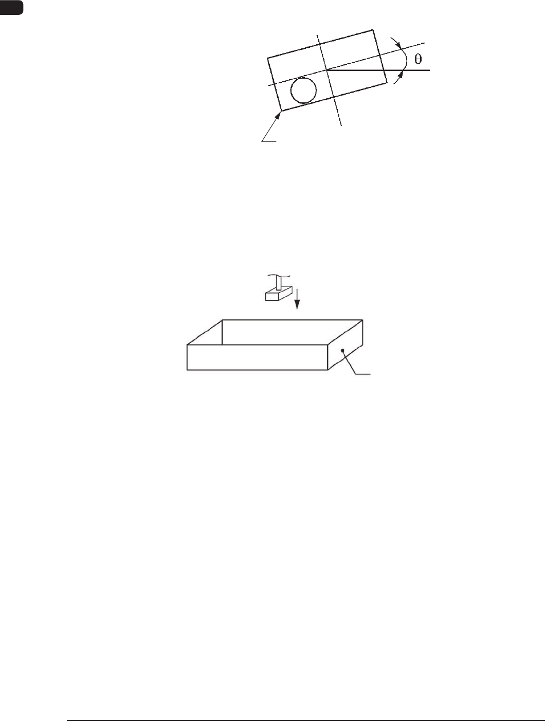
Recognition Correction (Angular Correction)
The picked component is adjusted to the angle (placement direction) of placement
specied in the pattern program by rotating the head. At this time, the angular
deviation (
q
) detected through component recognition is also corrected.
Component
F1A35
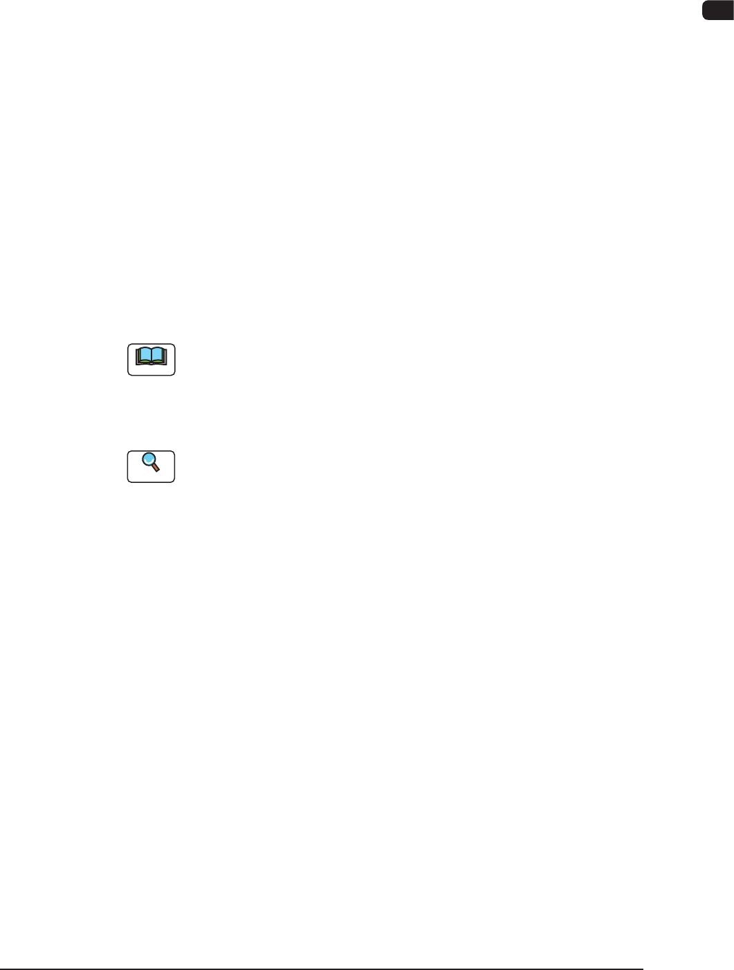
Component Discharge (Component Storage Box)
When a recognition error occurs during the component recognition, the placement
head moves to the component storage box and discharges the error-caused
component.
Component Storage Box
Component Discharge F1A36
1OM-1603
1-41
4. Surface Mounting Mechanism : Chap.1
1108-004
4.7 Component Placement
The placement head moves to the point (the coordinates for the placement)
specied in the pattern program for the PCB in the standby mode in the PCB
positioning section. At this time, the positional deviations (X, Y) measured
through the component recognition are adjusted correctly for proper component
picks.
The lowest limit of the vacuum nozzle is controlled according to the component
library data.
The solenoid valve closes and the component picked up by the vacuum nozzle is
placed on the PCB.
The front and rear beams take component placement and pickup actions repeatedly
in turns, realizing efcient and continuous component mounting.
4.8 PCB Output
The PCB where the components have already been placed is sent to the output
machine through the buffer.
Note
When the out-of-standard output method is used and the PCB transfer speed is
lower in the output machine, set the same transfer speed for the machine as that
in the output machine.
Set the "Output Machine Set Transfer Speed (Default Value: 300 [mm/sec])" to
the same value in the output machine on the "PCB Transfer Mode".
Reference
Refer to "3.2 PCB Transfer Mode" in "Chapter 2 (Volume 3)" for details.