1OM-1603-006_w.pdf - 第64页
1OM-1603 1-7 2. Name and Function of Each Section : Chap.1 1012-005 2.2.2 Feeder Ready Switches and Cover Lock Switches Cover Lock Switch ([Cover READY] Button) Feeder Ready Switch ([F2 READY] Button) Front Side of Machi…
1OM-1603
1-6
2. Name and Function of Each Section : Chap.1
1012-004
2.2 Mechanism for User Protection
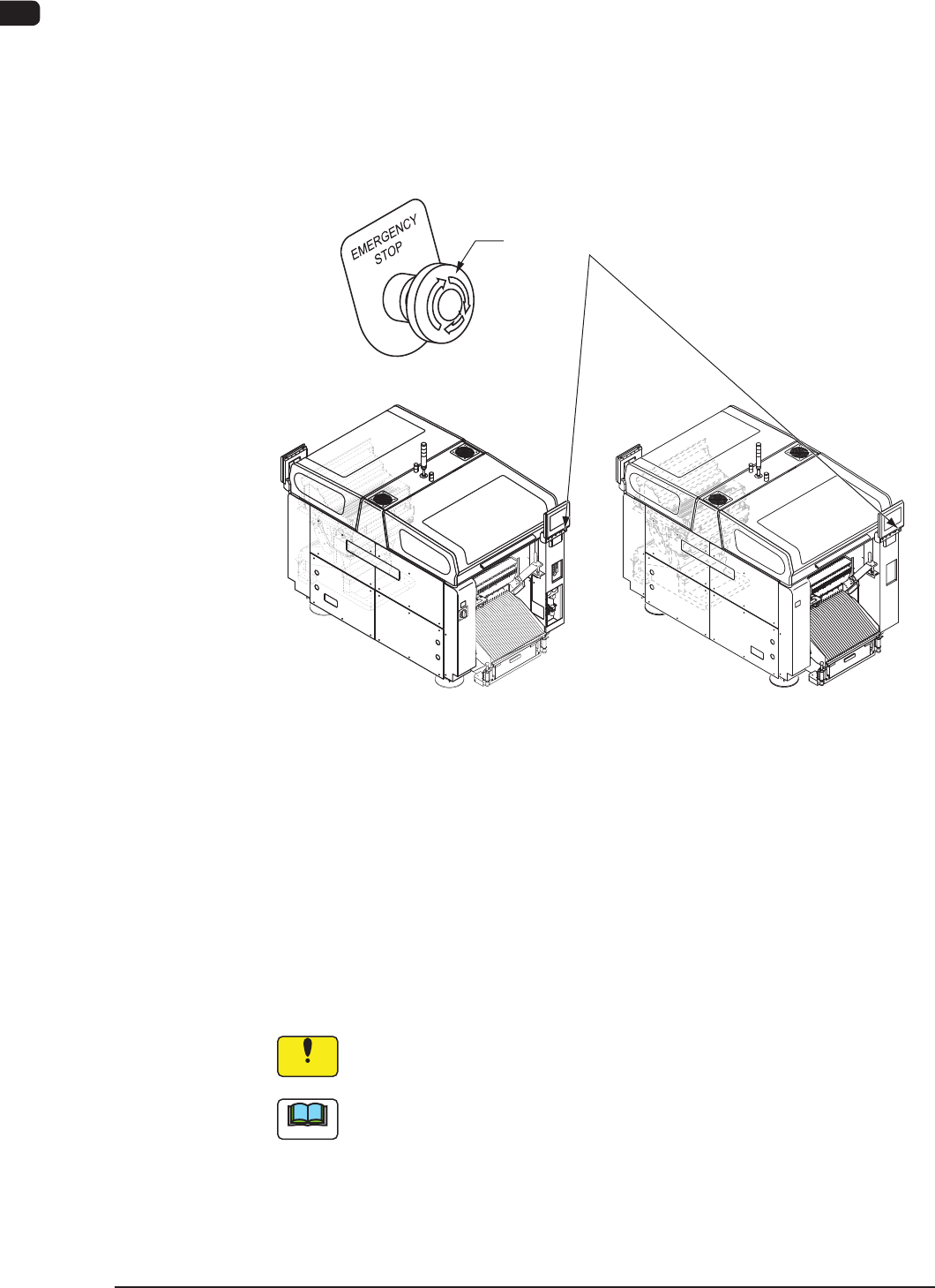
2.2.1 [EMERGENCY STOP] Switches
The [EMERGENCY STOP] switches can be used to stop the machine in an
emergency.
When one of the [EMERGENCY STOP] switches is pressed, the machine stops
immediately and the [POWER ON] button on the operation panel turns red.
[EMERGENCY STOP] Switches
Front Side of Machine Rear Side of Machine
F1A4
•
Locking the [EMERGENCY STOP] Switch
When one of the [EMERGENCY STOP] switches is pressed, the machine stops
and the switch is locked.
•
Unlocking the [EMERGENCY STOP] Switch
When one of the [EMERGENCY STOP] switch is pressed (locked), check and
remove the cause of the emergency stop. After that, recheck each section and
turn the switch clockwise to unlock.
Notice
The [EMERGENCY STOP] switches are used to intercept the controlled
power supply in an emergency.
Note
This machine is not provided with any emergency stop off function that can be
used to intercept the power supply to all loads in an emergency.
When "Emergency Switch Off" is required, it must be prepared outside the
machine on the customer side.
1OM-1603
1-7
2. Name and Function of Each Section : Chap.1
1012-005
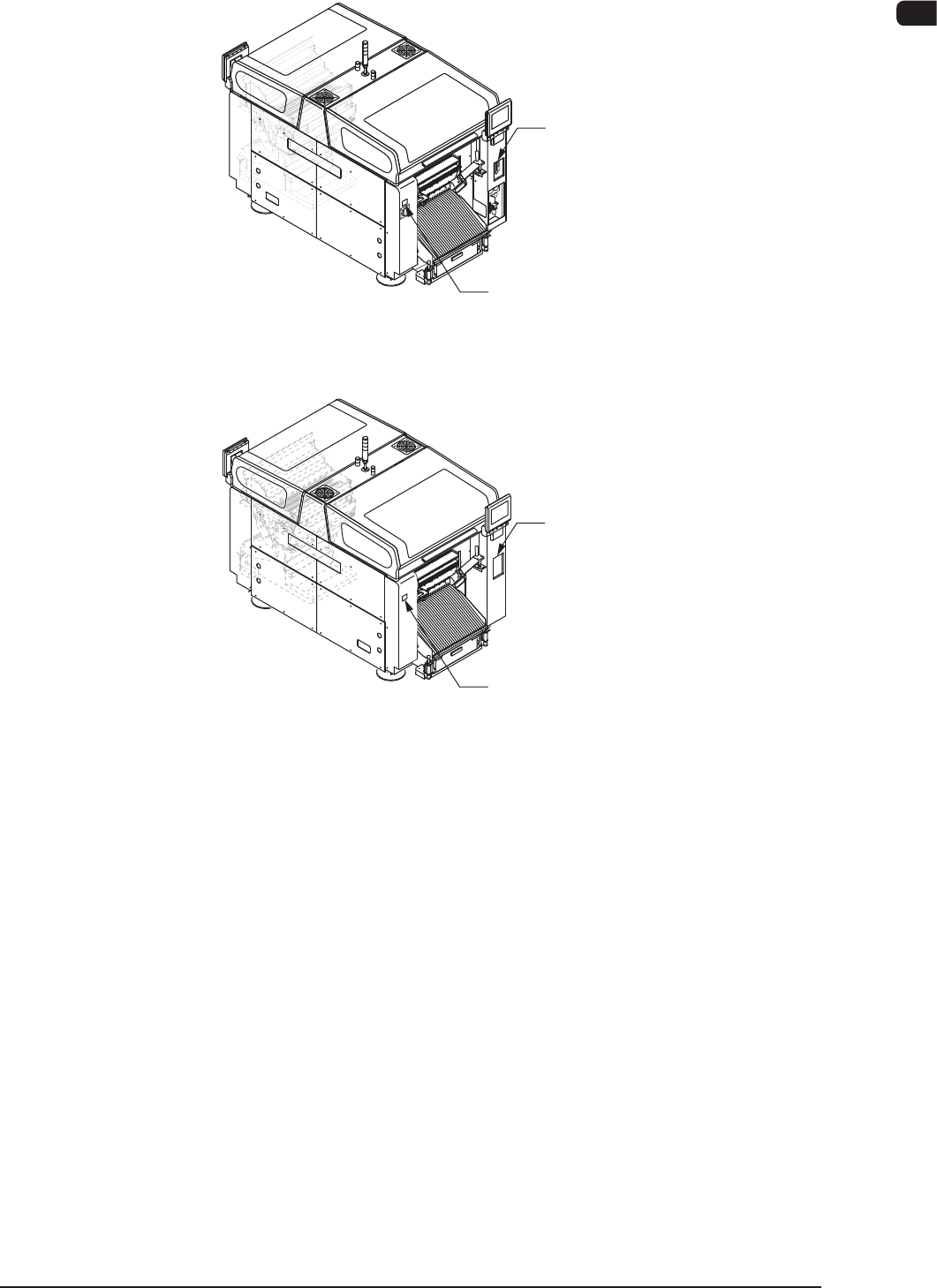
2.2.2 Feeder Ready Switches and Cover Lock Switches
Cover Lock Switch
([Cover READY] Button)
Feeder Ready Switch
([F2 READY] Button)
Front Side of Machine
Rear Side of Machine
Cover Lock Switch
([Cover READY] Button)
Feeder Ready Switch
([F1 READY] Button)
F1A5
1OM-1603
1-8
2. Name and Function of Each Section : Chap.1
2.2.2.1 Feeder Ready Switches
The feeder ready switches are used to indicate that the feeder bases are set ready
and each switch is employed in each feeder block.
When the [START] button is pressed, the feeder clamp is activated and when the
machine is stopped or paused, the feeder clamp is released.
Also, this function enables the operator to perform operations while checking the
feeder pickup sections.
LED ON
Switch ON (Short Push )
LED OFF
S witch Operations and Tr ansition of Machine Condition
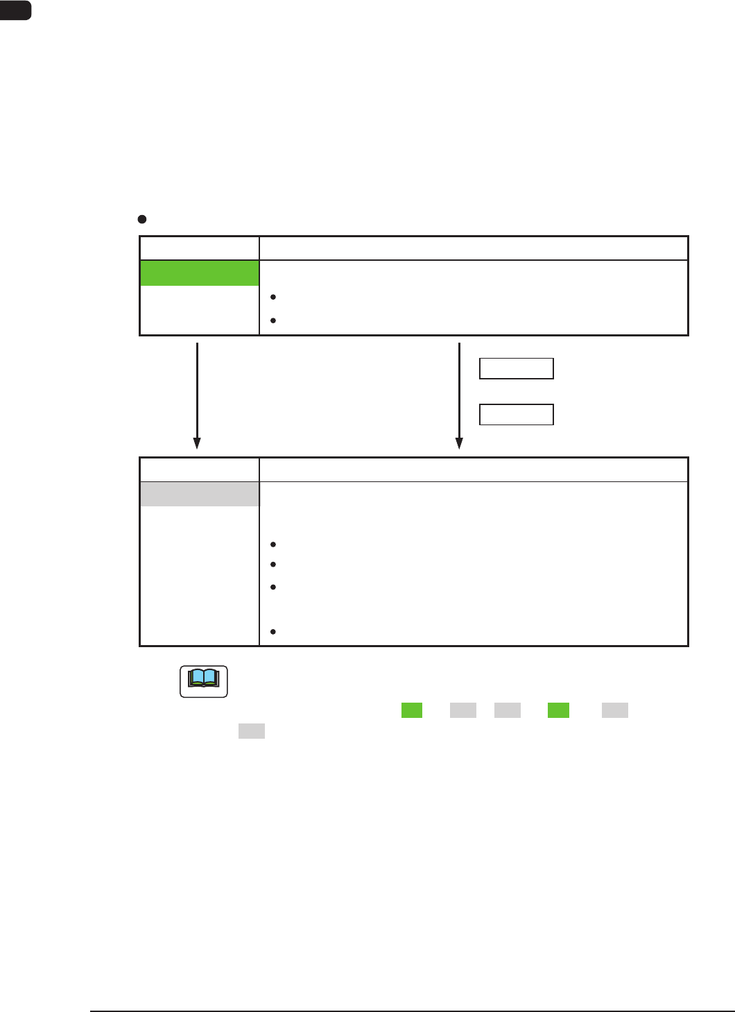
[Ordinary Operations with Machine in "STOP" (or "PAUSE") Mode]
Feeder Ready Switches
Switch Status Machine Status
Power Supply ( 24 V) to Feeders :
Switch Status Machine Status
LED OFF
" Replacement and Setup Operations of Feeder Bank
Carriage Cart" Possible
Power Supply ( 24
V) to Feeders :
Intercepted
F eeder
Attachment/Detachment Operation :
Possible
Power Supply to Connector for
feeder Base Installed on Main Machine
:
Intercepted
Not e
D uring the transition of the machine status along with the above-described
switch operations, the FEEDER READY switches flicker, regardless of a
LED lighting pattern such as "ON" to "OFF", "OFF" to "ON", or "OFF" to
"OFF".
+
+
Switch ON (Short Push)
Powere d
:
Unlocke d Feeder Base Drop Prevention
F eeder
Attachment/Detachment Operation :
Impossible
LED OFF
" Operation of Feeder Ready" Permitted by Operator
1108-006