1OM-1603-006_w.pdf - 第61页
1OM-1603 1-4 2. Name and Function of Each Section : Chap.1 1 108-006 2. Name and Function of Each Section 2.1 Appearance of Machine Note The gures in brackets show the reference item No. Light Tower (2.3.2) Front Operat…

1OM-1603
1-3
1. What is the modular mounter? : Chap.1
1012-004
•
Soft Mounting Nozzle
This nozzle can be used for soft component placement because it reduces
impacts caused due to upward wapage of PCBs which affects minute
components of 1005 size or less.
Minute component placement without two-step speed reduction becomes
possible for improved productivity.
Recognition Unit
•
Non-Stop Fly Batch Recognition
Components can be recognized collectively without stopping the heads
that are moving at high speed. This function is called "Non-Stop Fly Batch
Recognition".
Images without any distortion can be captured though the telecentric lens,
realizing the multiple recognition. This highly accurate multiple recognition
function is used to recognize up to 15 components collectively at high speed.
Cart Installation Section
•
Intelligent Motor-Driven Feeders
The adoption of motors for tape feeding realized highly accurate component
supply at high speed without any hindrance even for minute fragile (weak to
shocks) components.
If the machine is provided with spare bank feeder change carts, many more
types of components can be loaded onto the machine and feeder setup time
can be reduced.
The tape splicing function also enabled the continuous production (non-stop
operation of the machine).
PCB Transfer Section
•
PCB Height Measurement Feedback Function (Optional)
Before the machine places components on a PCB, the thickness of the PCB
upper surface is measured using a laser and is fed back to the height for
component placement.
It is possible to signicantly suppress stress imposed on components during
placement due to upward warpage of PCBs and reduce solder bridges for
high quality component placement.
1OM-1603
1-4
2. Name and Function of Each Section : Chap.1
1108-006
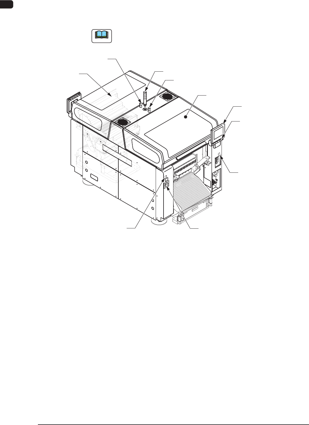
2. Name and Function of Each Section
2.1 Appearance of Machine
Note
The gures in brackets show the reference item No.
Light Tower (2.3.2)
Front Operation Panel
(2.3.4)
[EMERGENCY STOP]
Switch (2.2.1)
Auxiliary Lamp
Transparent Cover
(2.2.3)
Cover Lock Switch
([Cover READY] Button)
Power Breaker
(2.3.1)
Auxiliary Lamp
(2.3.3)
Front Side of Machine
Transparent
Cover (2.2.3)
(2.2.2.2)
Feeder Ready Switch
([F2 READY] Button)
(2.2.2.1)
F1A2
1OM-1603
1-5
2. Name and Function of Each Section : Chap.1
1108-006
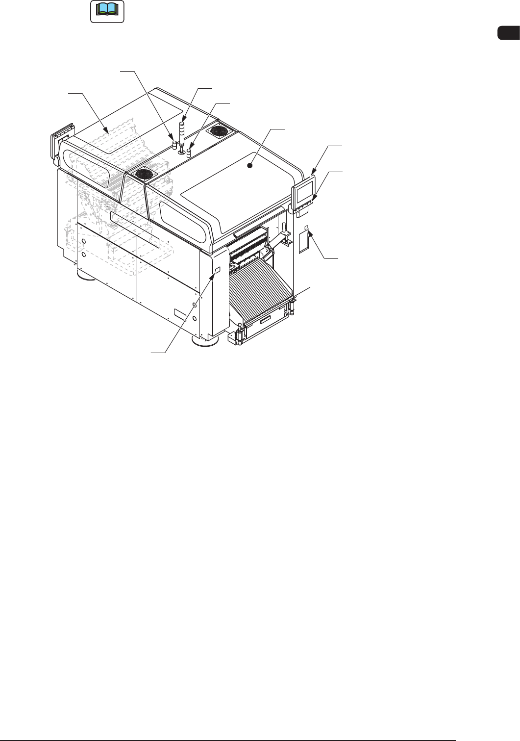
Note
The gures in brackets show the reference item No.
Light Tower (2.3.2)
Rear Operation Panel
(2.3.4)
[EMERGENCY STOP]
Switch (2.2.1)
Auxiliary Lamp
Transparent Cover
(2.2.3)
Cover Lock Switch
([Cover READY] Button)
(2.2.2.2)
Auxiliary Lamp
(2.3.3)
Transparent
Cover (2.2.3)
Rear Side of Machine
Feeder Ready Switch
([F1 READY] Button)
(2.2.2.1)
F1A3