1OM-1603-006_w.pdf - 第92页
1OM-1603 1-35 3. Mechanism for Surface Mounting : Chap.1 1012-004 3.9.3 Back Lighting Recognition System The gure below shows the sectional view of the recognition section in the back lighting recognition system and the…
1OM-1603
1-34
3. Mechanism for Surface Mounting : Chap.1
1012-004
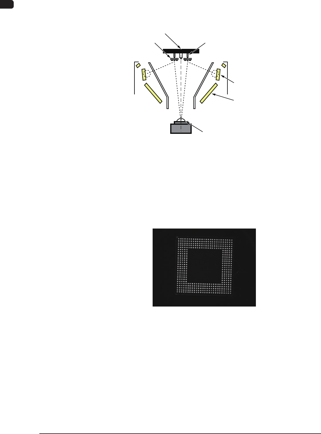
3.9.2 Front Lighting Recognition System (For BGA Components)
The gure below shows the sectional view of the recognition section in the front
lighting recognition system (for BGA components) and the ow of lights for the
recognition.
Vacuum nozzle Components
Back Lighting
Front Lighting 3
(BGA Lighting)
Front Lighting 1
Front Lighting 2 (Coaxial Lighting)
CCD Camera
Scope
Diffusion Plate
F1A29
The light emitted from the lamp for front lighting 3 meets the balls located on the
bottom of the BGA component.
The reected light goes into the CCD camera through the monocular.
The captured image of the balls looks like a doughnut. That is, the CCD camera
captures the image of the balls to determine where the balls are located or how the
balls are arranged (missing balls, etc.).
F1A27-1
1OM-1603
1-35
3. Mechanism for Surface Mounting : Chap.1
1012-004
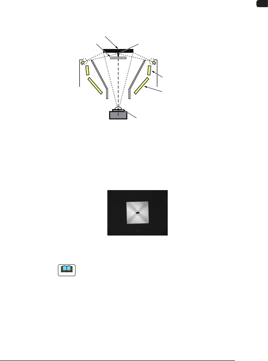
3.9.3 Back Lighting Recognition System
The gure below shows the sectional view of the recognition section in the back
lighting recognition system and the ow of lights for the recognition.
When a component like the shadowed one in the gure is used, the outline of the
component is recognized through the back lighting.
Vacuum nozzle Components
Back Lighting
Front Lighting 3
(BGA Lighting)
Front Lighting 1
Front Lighting 2 (Coaxial Lighting)
CCD Camera
Scope
Diffusion Plate
F1A30
The lights emitted from the lamps for back lighting meet the diffusion plate and
reect to the component.
At this time, the lights that do not meet the component go into the CCD camera
through the monocular.
That is, the CCD camera captures the outline of the component.
Example : Captured Image for Recognition
F1A31
Note
In the case of the back lighting, the non-stop y batch recognition is
not available.
1OM-1603
1-36
4. Surface Mounting Mechanism : Chap.1
1108-005
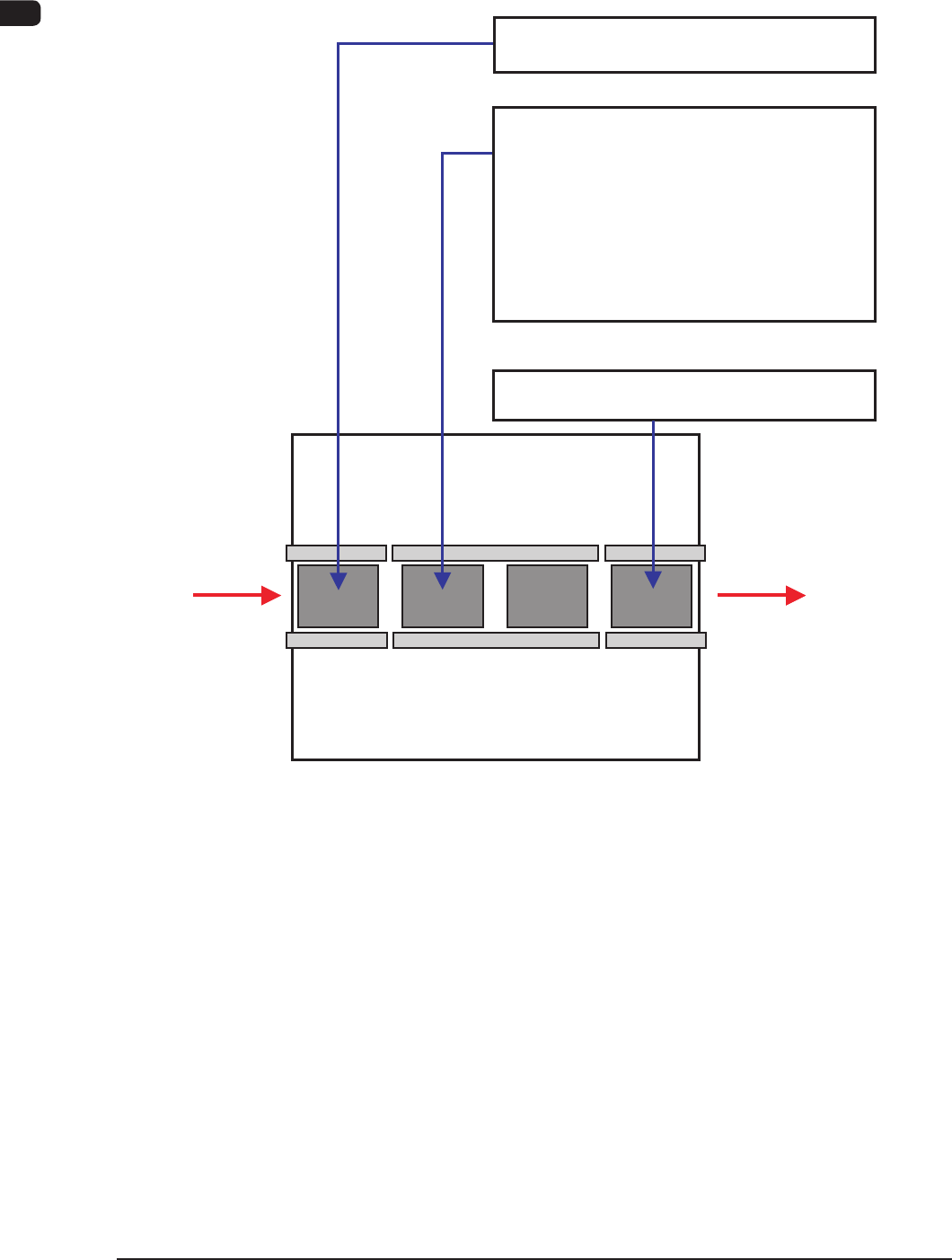
4. Surface Mounting Mechanism
Described roughly below is how the components are placed on the PCB.
PCB Input Chapter 1
PCB Positioning Chapter 1
PEC Recognition Chapter 1
Component Supply Chapter 1
Component Picks Chapter 1
Component Recognition
Chapter 1
Component Placement
Chapter 1
PCB Output Chapter 1
4.1 in
4.2 in
4.3 in
4.4 in
4.5 in
4.6 in
4.7 in
4.8 in
Input
Machine
Output
Machine
PCB Input
Section
PCB
Positioning
"L"
Section
PCB
Positioning
"R"
Section
PCB Output
Section
Flow Chart for Surface Mounting
F1A32