00191413-01.pdf - 第295页
User Manual Line Computer UNIX 9 Production Tools / Feeders Software Version 501.xx 01/99 Issue 9.1 Feeder Editor 9 - 11 9.1.3. 3 S etting Area The settin g area c ontains b uttons for the setti ngs "Left side"…
9 Production Tools / Feeders User Manual Line Computer UNIX
9.1 Feeder Editor Software Version 501.xx 01/99 Issue
9 - 10
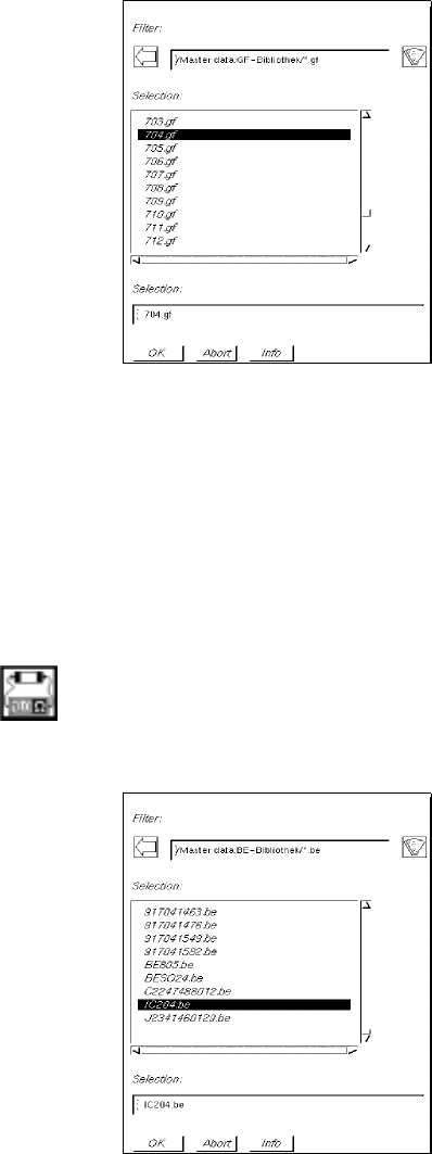
● Select GF-file 704.gf by double-clicking (or enter name of the GF-file in the selection field and
confirm with OK).
The FSB is closed and the number of the selected package form is entered in the editing field
"Package form" in the main window of the Feeder Editor.
In the "GF name" field the comment ("PLCC68") entered in the Package Form Editor is displayed.
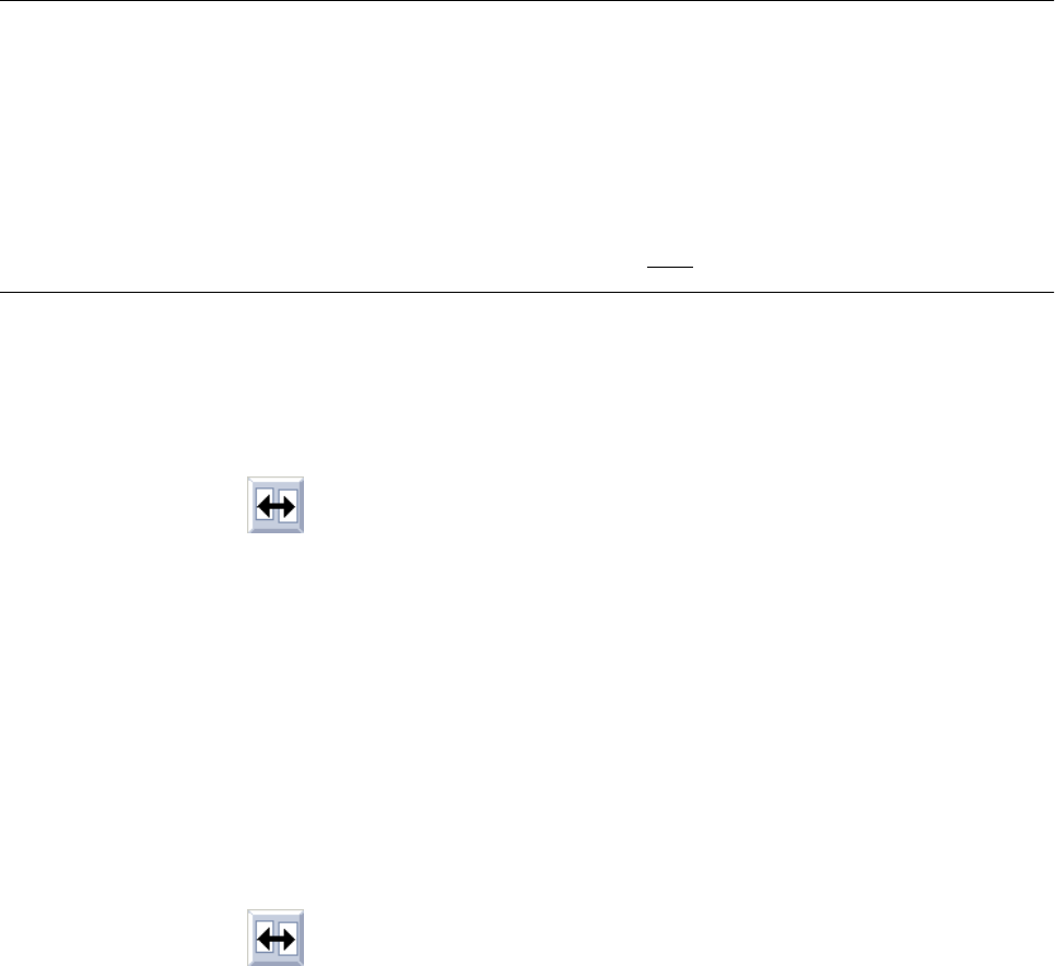
Example: Changing from package form "600" to component "IC204"
Procedure:
● Click on icon
The FSB containing a selection of the files of all previously defined components is opened:
● Select component file IC204.be by double-clicking (or enter name of the component file in the sel-
ection field and confirm with OK).
The FSB is closed and the name of the selected component is entered in the editing field "Com-
ponent" in the main window of the Feeder Editor.
In the editing field "Package form" the number of the package form allocated to the component
"IC204", and in the "GF name" field the comment ("PLCC100") entered in the Package Form
Editor are displayed (see Fig. 9.1.2).
User Manual Line Computer UNIX 9 Production Tools / Feeders
Software Version 501.xx 01/99 Issue 9.1 Feeder Editor
9 - 11
9.1.3.3 Setting Area
The setting area contains buttons for the settings "Left side", "Line" and "Right side".
By clicking on the appropriate button it is possible to assign a given feeder, which is subsequently to be selected
from the selection field "Placeable feeders", either to a specific side, or without any restrictions.
NOTE
If the "Line" button is activated, this means that any subsequently defined allocations of feeders apply to the
feeder parts on both sides of the line on which they can be set up.
If a particular machine type or a feeder part of a particular machine type is selected, all buttons in the
setting area are deactivated so that the allocation only applies to the selected machine type or the
selected feeder part of the machine type.
Caution! When allocating package forms to waffle-pack trays, "Line" must be selected as the location.
Procedure for the allocation of a feeder to a package form on the left or right side:
● Select the package form (see section 9.1.3.2).
● Activate icon in the command area (see section 9.1.3.4).
● Click on the Left side or Right side button.
All feeder parts on the left side or right side of the line are highlighted in green.
● Click on feeder in the selection field "Placeable feeders".
The name of the selected feeder is displayed in the selection field "Feeder" followed by the letter
"L" or "R". This means that the current package form can be supplied by means of this feeder,
either from the left or right side.
Procedure for the allocation of a feeder to a package form on the machine type "SIPLACE80F", right
side of the machine:
● Select the package form (see section 9.1.3.2).
● Activate icon in the command area.
● Click on feeder part on the right side of the machine type "SIPLACE80F" (see Fig. 9.1.2).
The feeder part is highlighted in green.
● Click on feeder in the selection field "Placeable feeders".
This means that the feeder entered may be set up on the right feeder part of the machine type
"SIPLACE80F" only.
The name of the allocated feeder, the machine type and the machine side on which the feeder
can be set up are displayed in the selection field "Feeder".
Example: FD~S_G_8_EL S_SIP_80_F R
9 Production Tools / Feeders User Manual Line Computer UNIX
9.1 Feeder Editor Software Version 501.xx 01/99 Issue
9 - 12
9.1.3.4 Command Area
The commands are symbolized by means of icons. They determine the mode (selection mode, allocation mode
or deletion mode) in which the Feeder Editor is to operate.
NOTE
Upon opening, the Feeder Editor is initially in the selection mode.
- (Select)
When this icon is active (displayed in reverse video, with arrow pointing from the lower left to the upper
right), the editor is in the selection mode. It is possible to select machine types or individual elements
from the display area, and feeding units from the selection fields, by clicking the left mouse button.
● Click on icon in the command area.
(The arrow in the icon now points to the upper right).
● Click on machine element (feeder part) in the display area (see Fig. 9.1.2).
The selected element is highlighted in green.
In the selection field "Placeable feeders" all feeders or waffle-pack trays are displayed that can be
set up on the selected element.
NOTE
Double-clicking on an entry in the selection field "Placeable feeders" causes the window for
editing the feeder or waffle-pack tray data to be opened (see section 9.1.4).
- (Allocate)
When this icon is active, the editor is in the allocation mode.
● Click on icon in the command area.
● Click on, for example, the Line button in the setting area to allocate the subsequently selected
feeding unit without any restrictions (see section 9.1.3.3). All machine types are now highlighted
in green.
● Select the feeder or waffle-pack tray from the selection field "Placeable feeders" .
The selected unit is displayed in the "Feeder" selection field.
NOTE
Further allocation possibilities are described in section 9.1.4.
Double-clicking on an entry in the selection field "Placeable feeders" causes the window for
editing the feeder of waffle-pack tray data to be opened (see section 9.1.4).