00191413-01.pdf - 第568页
17.3 Description of Components and PCBs User Manual Line Computer UNIX 17.3.2 PCB 2: Focus on Packa g e Form Description Software Vers ion 501.xx 01/99 Issue 17 - 36 PCB de scription Defin ing fiduc ials contin ued from …
User Manual Line Computer UNIX 17.3 Description of Components and PCBs
Software Version 501.xx 01/99 Issue 17.3.2 PCB 2: Focus on Packa
g
e Form Description
17 - 35
17.2.2.2 Component Description
To open the Component Editor for a component, proceed as follows:
104.On the desktop click on the icon the the Component Editor .
The file selection window is opened.
105.Click on the
Selection
editin
g
field.
106.Enter the name of the component, here:
Comp4.be
, click on the
OK
button.
The Component Editor is opened.
To enter the component data, proceed as follows:
107.Click on the
Comment
editin
g
field, enter a comment that is a uni
q
ue description of the component, here:
Chip 2220
.
108.Click on the
Package form
editin
g
field, enter the packa
g
e form number, here:
1501
.
109.In the Handlin
g
selection field activate the appropriate buttons, here:
Placing
.
110.In the CRDL selection area activate the appropriate buttons, here:
No check
.
111.Click on the
Save
option on the
FILE
menu.
The component data are saved.
112.Click on the
Quit
option on the
FILE
menu.
The Component Editor is closed.
113.Carr
y
out the component description for the remainin
g
components analo
g
ousl
y
, here:
Comp5.be
and
Comp6.be
.
17.2.2.3 Adhesive Pattern Description
For the new packa
g
e forms an adhesive pattern is automaticall
y
adopted from the DM-Bibliothek.
17.2.2.4 PCB Description
To open the PCB Editor, proceed as follows:
114.On the desktop click on the icon of the PCB Editor .
The file selection window is opened.
115.Click on the
Selection
editin
g
field.
116.Enter the name of the PCB
,
here:
Example_2.la
and click on the
OK
button.
A dialo
g
box is opened.
117.Click on the
TYPE
editin
g
field.
118.Enter a t
y
pe desi
g
nation, here:
board_1
and click on the
OK
button.
The PCB Editor is opened. The PCB is displa
y
ed as a rectan
g
le.
To specify the position of the PCB in the machine, proceed as follows:
119.Activate the Coordinate s
y
stem icon .
120.Click on the PCB
(
rectan
g
le
)
.
A dialo
g
box with the displa
y
of four coordinate s
y
stems is opened.
121.Click on a coordinate s
y
stem, here:
0°
.
122.Click on the
OK
button.
The dialo
g
box is closed.
17.3 Description of Components and PCBs User Manual Line Computer UNIX
17.3.2 PCB 2: Focus on Packa
g
e Form Description Software Version 501.xx 01/99 Issue
17 - 36
PCB description
Defining fiducials
continued from pa
g
e 17-34
Entering dimensions
of the PCB
continued on pa
g
e 17-38
Cluster Editor
Fiducial Editor
User Manual Line Computer UNIX 17.3 Description of Components and PCBs
Software Version 501.xx 01/99 Issue 17.3.2 PCB 2: Focus on Packa
g
e Form Description
17 - 37
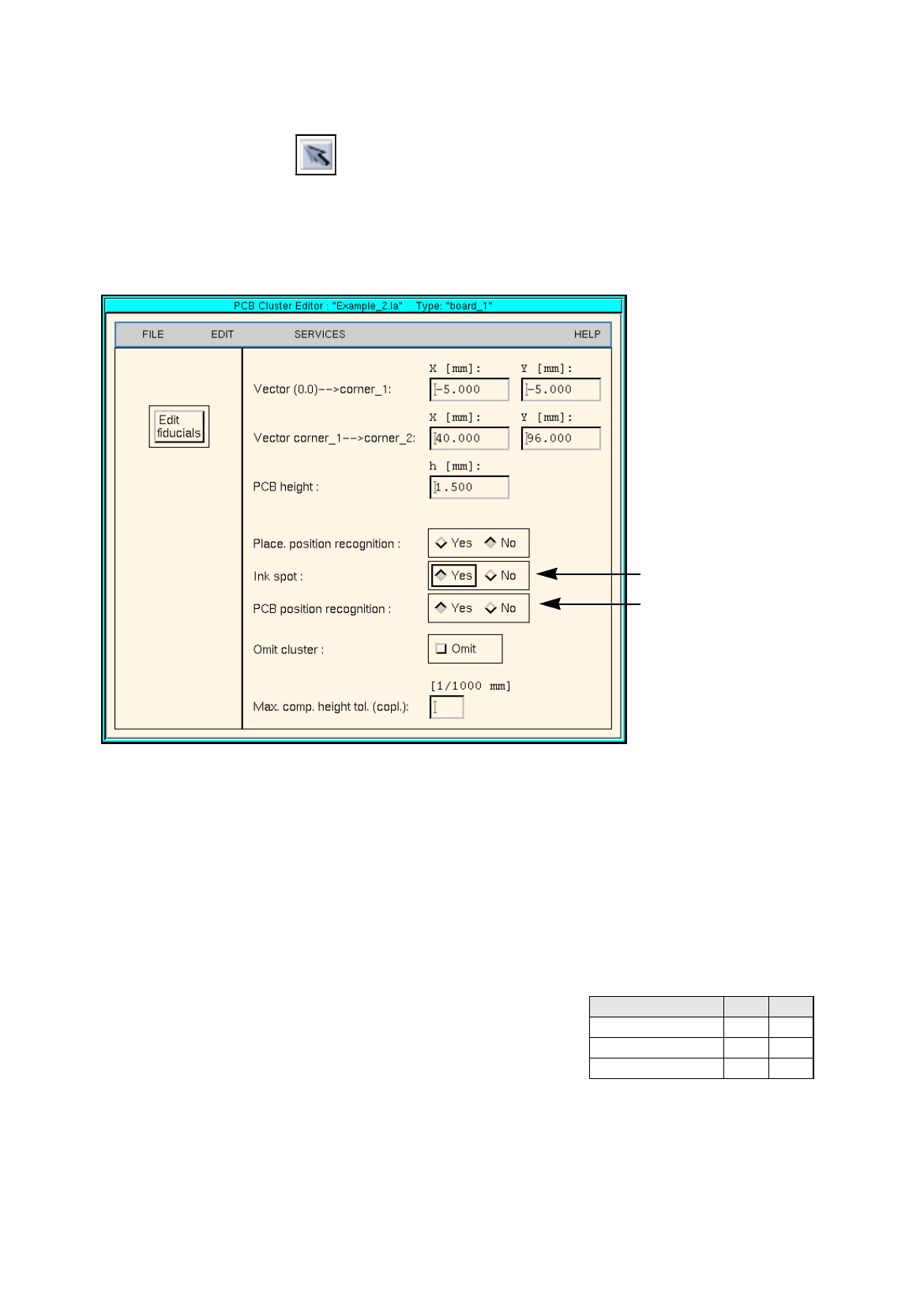
To enter the dimensional data of the PCB, proceed as follows:
123.Activate the Select icon .
124.Click on the PCB
(
rectan
g
le
)
.
The rectan
g
le is hi
g
hli
g
hted in
g
reen.
125.Click on the
Cluster Editor
option on the
SERVICES
menu.
The Cluster Editor is opened.
126.Enter the dimensions of the PCB. See Fi
g
. 17.3.4 on pa
g
e 17-20 and Fi
g
. 17.3.5 .
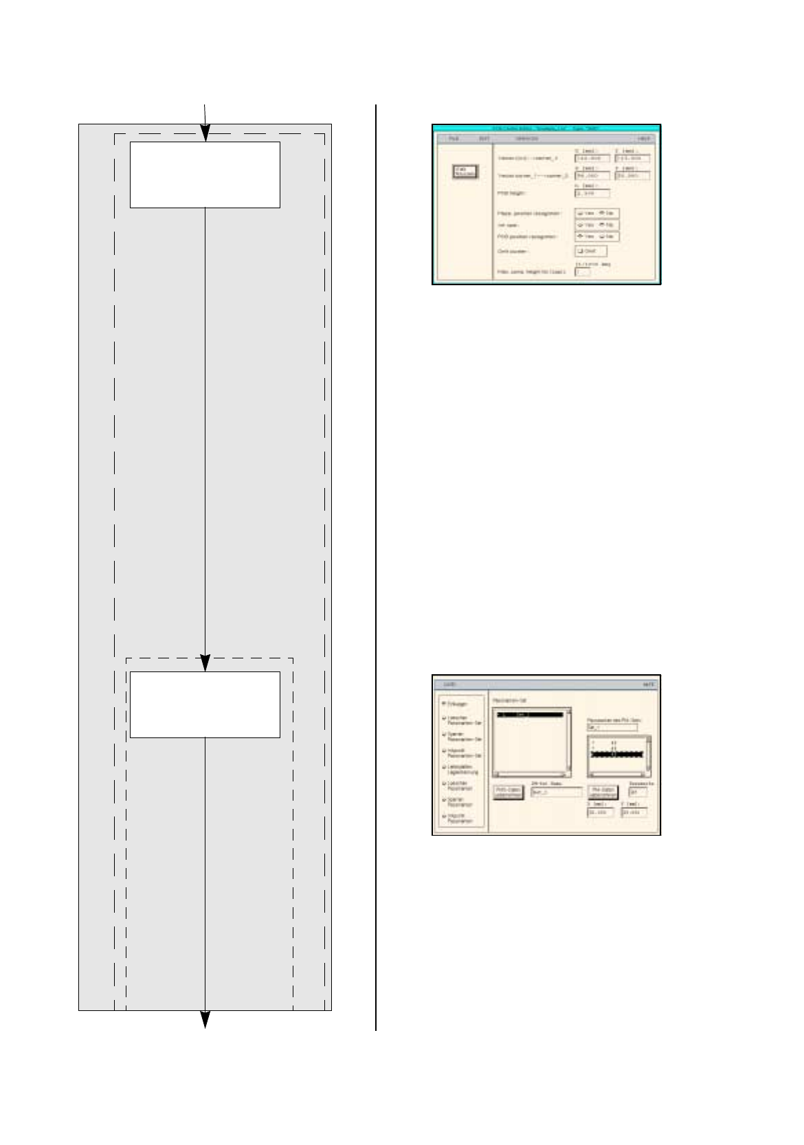
Fig. 17.3.5 Cluster Editor for PCB 2
To define the fiducials, proceed as follows:
127.In the Cluster Editor click on the
Edit fiducials
button.
The Fiducial Editor is opened.
128.Activate the
Insert
button.
129.Click on the
Fiducial set name
editin
g
field.
130.Enter a name for the new fiducial set, here:
Set_1
.
131.Click on the
Accept fiducial set
button.
The fiducial set Set_1
appears on the fiducial list.
132.Click on fiducial set Set_1 on the fiducial list.
133.Click on the
Fiducial
editin
g
field.
134.Enter the fiducial number for the first fiducial, here:
48
.
135.Click on the editin
g
fields for the coordinates, enter coordinates
(
do not confirm with Enter ke
y
!
)
, here: see chart:
136.Click on the
Accept fiducial data
button.
The data of the fiducial are transferred to the list of the fiducials of the fiducial set.
137.Define the remainin
g
fiducials accordin
g
l
y
, here:
fiducials
48
and
48
.
138.Activate the
PCB position recognition
button.
139.Click on the fiducial set Set_1 on the fiducial list.
The fiducial set
Set_1
is marked b
y
a preceedin
g
L
for PCB position reco
g
nition.
Fiducial number X Y
48 30 0
48 0 86
48 30 86
Activate ink spot
Activate PCB pos. reco
g
nition