00191413-01.pdf - 第567页
User Manual Line Computer UNIX 17.3 Description of Components and PCBs Software Version 501.xx 01/99 Issue 17.3.2 PCB 2: Focus on Packa g e Form Description 17 - 3 5 17.2.2.2 Component Description To open the Component E…
17.3 Description of Components and PCBs User Manual Line Computer UNIX
17.3.2 PCB 2: Focus on Packa
g
e Form Description Software Version 501.xx 01/99 Issue
17 - 34
The adhesive pattern description is dispensed with.
Opening the
Component Editor for
a component
Entering component
data
Component Editor
Adh. pattern description
Starting the PCB
Editor for a PCB
Entering the position
of the PCB in the
machine
PCB description
continued on pa
g
e 17-36
continued from pa
g
e 17-32
User Manual Line Computer UNIX 17.3 Description of Components and PCBs
Software Version 501.xx 01/99 Issue 17.3.2 PCB 2: Focus on Packa
g
e Form Description
17 - 35
17.2.2.2 Component Description
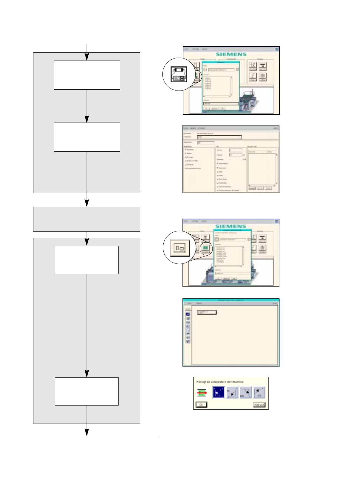
To open the Component Editor for a component, proceed as follows:
104.On the desktop click on the icon the the Component Editor .
The file selection window is opened.
105.Click on the
Selection
editin
g
field.
106.Enter the name of the component, here:
Comp4.be
, click on the
OK
button.
The Component Editor is opened.
To enter the component data, proceed as follows:
107.Click on the
Comment
editin
g
field, enter a comment that is a uni
q
ue description of the component, here:
Chip 2220
.
108.Click on the
Package form
editin
g
field, enter the packa
g
e form number, here:
1501
.
109.In the Handlin
g
selection field activate the appropriate buttons, here:
Placing
.
110.In the CRDL selection area activate the appropriate buttons, here:
No check
.
111.Click on the
Save
option on the
FILE
menu.
The component data are saved.
112.Click on the
Quit
option on the
FILE
menu.
The Component Editor is closed.
113.Carr
y
out the component description for the remainin
g
components analo
g
ousl
y
, here:
Comp5.be
and
Comp6.be
.
17.2.2.3 Adhesive Pattern Description
For the new packa
g
e forms an adhesive pattern is automaticall
y
adopted from the DM-Bibliothek.
17.2.2.4 PCB Description
To open the PCB Editor, proceed as follows:
114.On the desktop click on the icon of the PCB Editor .
The file selection window is opened.
115.Click on the
Selection
editin
g
field.
116.Enter the name of the PCB
,
here:
Example_2.la
and click on the
OK
button.
A dialo
g
box is opened.
117.Click on the
TYPE
editin
g
field.
118.Enter a t
y
pe desi
g
nation, here:
board_1
and click on the
OK
button.
The PCB Editor is opened. The PCB is displa
y
ed as a rectan
g
le.
To specify the position of the PCB in the machine, proceed as follows:
119.Activate the Coordinate s
y
stem icon .
120.Click on the PCB
(
rectan
g
le
)
.
A dialo
g
box with the displa
y
of four coordinate s
y
stems is opened.
121.Click on a coordinate s
y
stem, here:
0°
.
122.Click on the
OK
button.
The dialo
g
box is closed.
17.3 Description of Components and PCBs User Manual Line Computer UNIX
17.3.2 PCB 2: Focus on Packa
g
e Form Description Software Version 501.xx 01/99 Issue
17 - 36
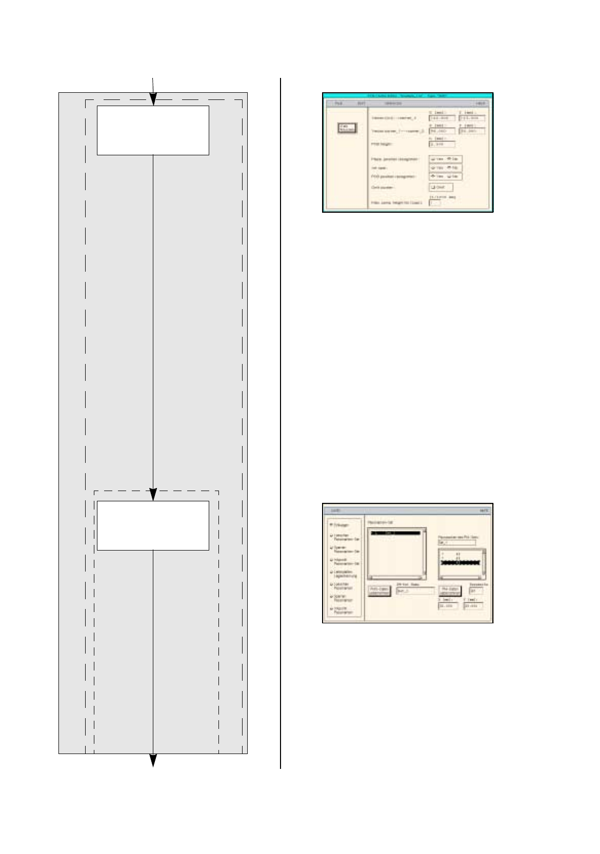
PCB description
Defining fiducials
continued from pa
g
e 17-34
Entering dimensions
of the PCB
continued on pa
g
e 17-38
Cluster Editor
Fiducial Editor