KE-750_QA表.pdf - 第31页
FUNCTION NAME Centering Pin Sinkage Detect ion Function/Performance CHECK/ADJUSTMENT METHODS (REMEDIAL ACT ION PROCEDURE) ASSURED QUALITY Reliability QUALITY CHARACTERISTI CS (SPECIFIC ATION VALUES) CATEGORY Safety Produ…
FUNCTION NAME Stopper Assembly PWB Detection Function/Performance CHECK/ADJUSTMENT METHODS (REMEDIAL ACTION PROCEDURE)
ASSURED QUALITY Reliability
QUALITY CHARACTERISTICS (SPECIFICATION VALUES) CATEGORY Safety
Product Image
ROLE IN FUNCTION (MEANING OF SPECIFICATION VALUES)
POSSIBLE MALFUNCTIONS (CAUSED BY INCORRECT SPECIFICATION VALUES)
COMPONENTS
NO. Part No. Part Name Associated Quality Characteristics
1 E94657250A0 Stop sensor cable assembly
2 E94667250A0 C. OUT sensor cable assembly
3 SL4031291SC 9465/9466 SEMS cap MODEL KE-750/760
4 UNIT Transport REF. NO.
5
NAME
1
6 FUNCTION Stopper Assembly PWB
7
NAME Detection
8
9
10
QA Table
E2130725OAO
Stopper L assembly
Press against right
side of slit. (8)
116 (Be careful abou
t
contact with stopper tip.)
E2125725OAO
Stopper R assembly
116 (Be careful abou
t
contact with stopper tip.)
Press against left
side of slit. (8)
C. OUT senso
r
Stop senso
r
A
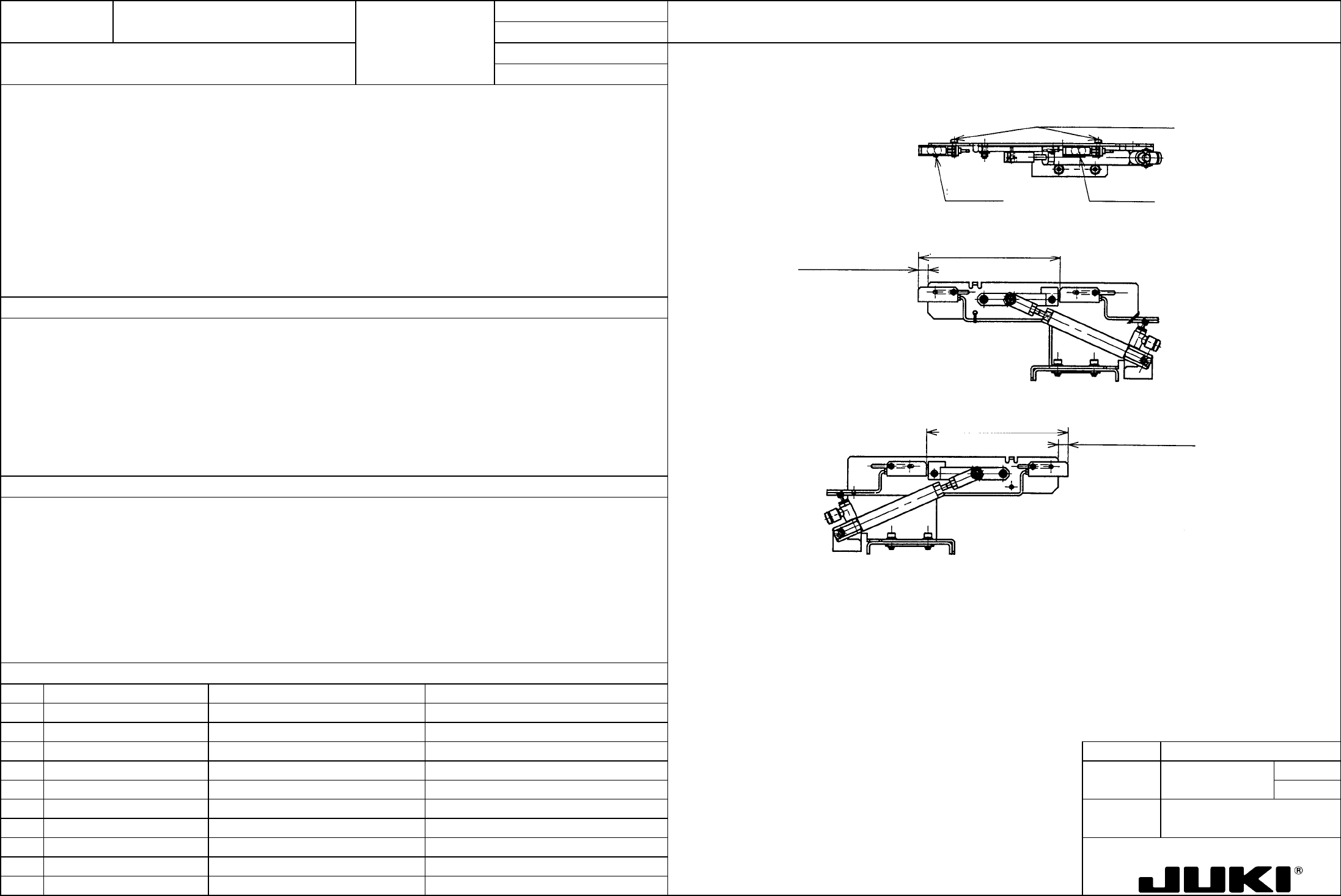
djusting screws (SL4031291SC)1. Stop sensor position: (8 mm) (See Fig. on the right.)
2. C. OUT sensor position 116 mm (See Fig. on the right.)
1. CENT motor stop signal trigger generation timing
2. IN motor start trigger generating timing (when transporting PWBs from the IN buffer to center buffer)
1. Severe collision of the PWB with the stopper due to insufficient deceleration of PWB. (Solution: Make the value smaller
than 8, which, however, results in further beyond the stopper frame.)
PWB failing to reach the stopper due to excessive deceleration. (Solution: Make the value larger than 8.)
2. Increased PWB transport tact time due to delayed starting of IN motor.
FUNCTION NAME Centering Pin Sinkage Detection Function/Performance CHECK/ADJUSTMENT METHODS (REMEDIAL ACTION PROCEDURE)
ASSURED QUALITY Reliability
QUALITY CHARACTERISTICS (SPECIFICATION VALUES) CATEGORY Safety
Product Image
ROLE IN FUNCTION (MEANING OF SPECIFICATION VALUES)
POSSIBLE MALFUNCTIONS (CAUSED BY INCORRECT SPECIFICATION VALUES)
COMPONENTS
NO. Part No. Part Name Associated Quality Characteristics
1 E94837250A0 T-pin sensor cable assembly
2 E2148721000 Sensor bracket R
3 E2147721000 Sensor bracket L MODEL KE-750/760
4 UNIT Transport REF. NO.
5
NAME
2
6 FUNCTION Centering Pin Sinkage
7
NAME Detection
8
9
10
QA Table
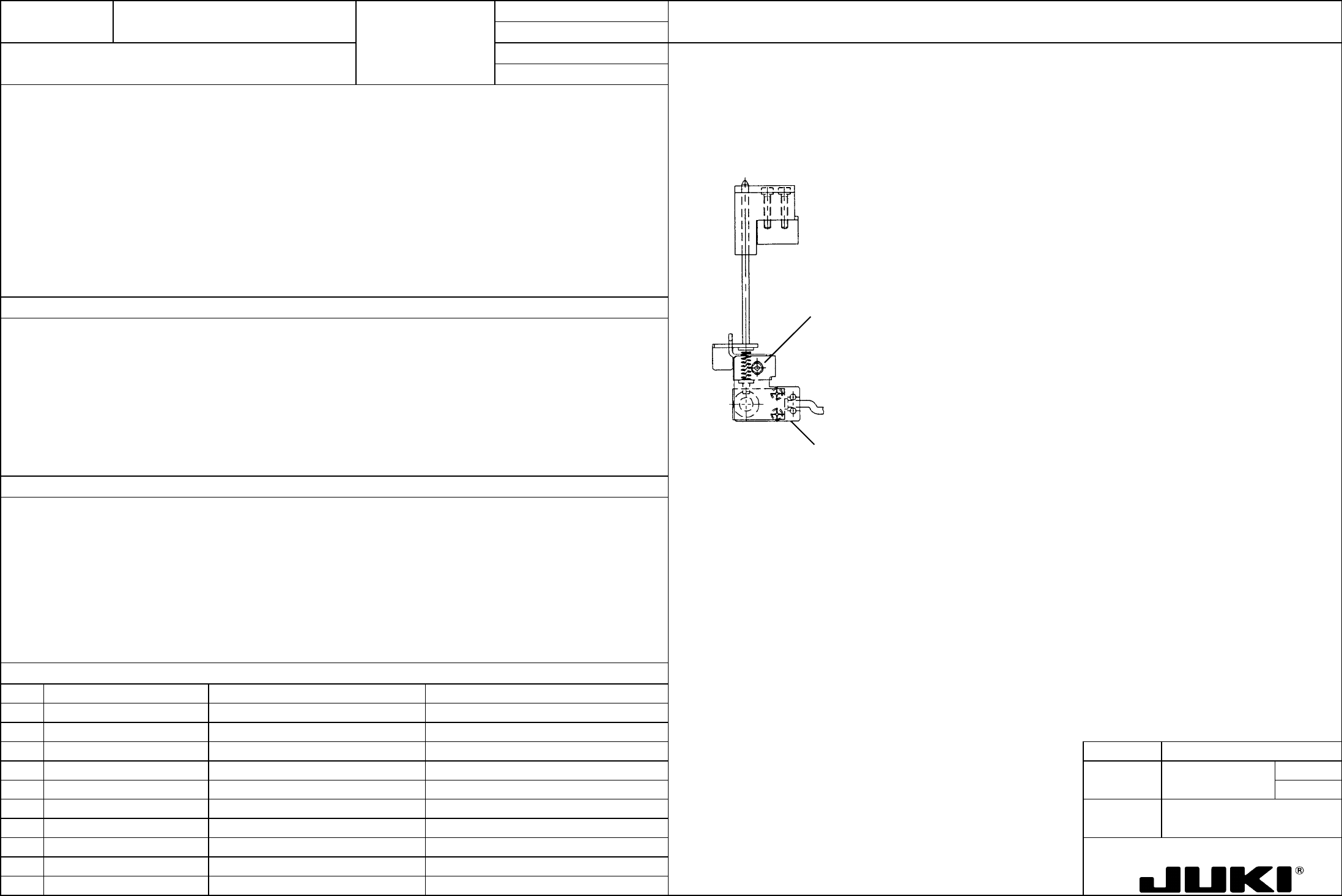
With the reference pin in 1.5 0/-0.5 mm lowered position, loosen the adjusting screw and move the sensor bracket up and
down to activate the sensor; then, at that point, secure the sensor bracket in position.
1. The sensor is to be activated when the reference pin lowers 1.5 0/-0.5 mm.
Sensor bracket
Adjusting scre
w
SL6030692TN
1. Detects that the centering pin does not fit into the reference hole.
1. The centering pin does not fit into the reference hole, which means that the components are transported with the PWB
incorrectly positioned, resulting in the components being placed at wrong positions.
FUNCTION NAME Transport Unit Parallel Alignment Function/Performance CHECK/ADJUSTMENT METHODS (REMEDIAL ACTION PROCEDURE)
ASSURED QUALITY Reliability
QUALITY CHARACTERISTICS (SPECIFICATION VALUES) CATEGORY Safety
Product Image
ROLE IN FUNCTION (MEANING OF SPECIFICATION VALUES)
POSSIBLE MALFUNCTIONS (CAUSED BY INCORRECT SPECIFICATION VALUES)
COMPONENTS
NO. Part No. Part Name Associated Quality Characteristics
1 E2044725000 Transport rail FC
2
3 MODEL KE-750/760
4 UNIT Transport REF. NO.
5
NAME
3
6 FUNCTION Transport Unit Parallel
7
NAME Alignment
8
9
10
QA Table
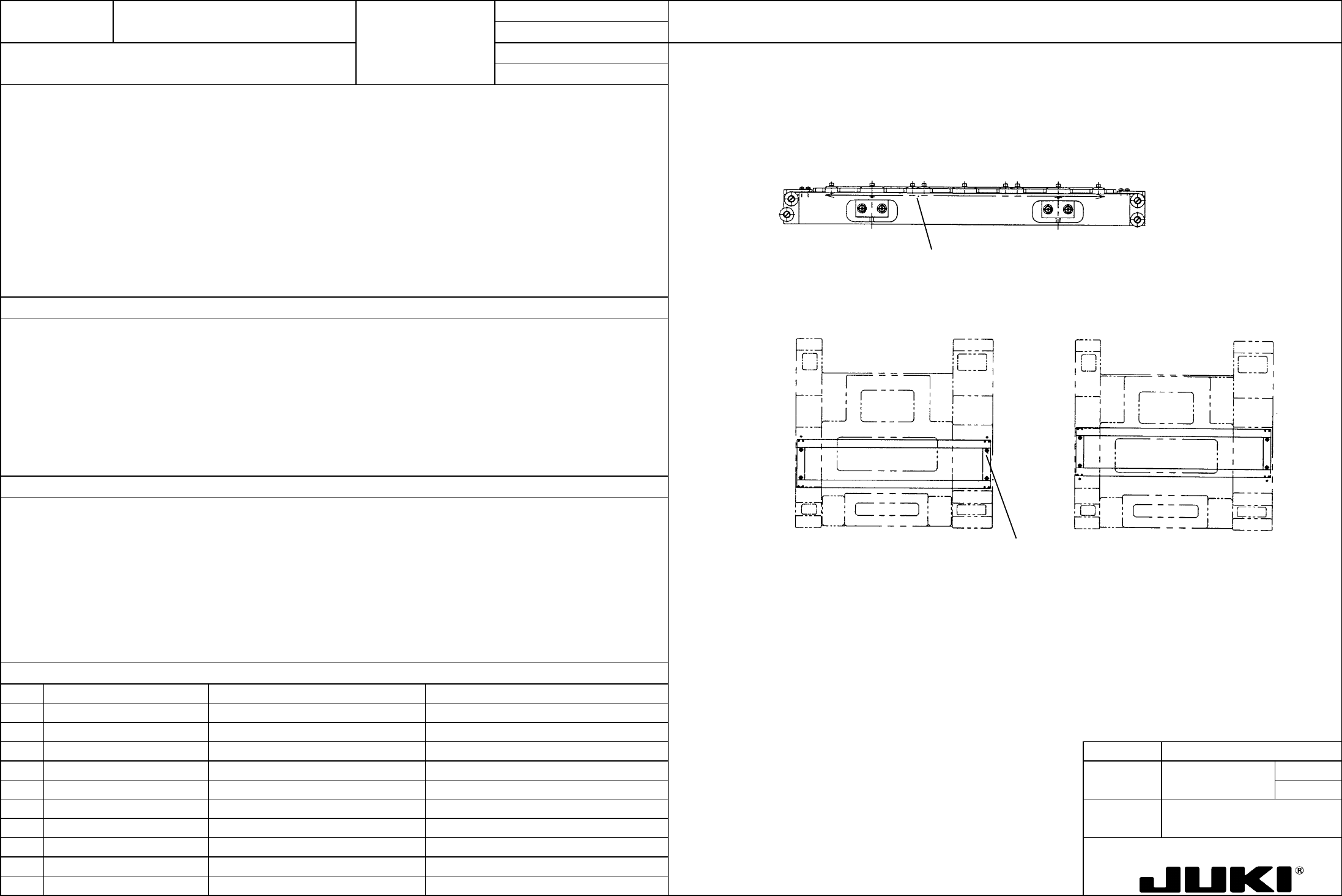
Mount a dial indicator to camera bracket D of the head. When the measurement point indicated below of transport rail F
becomes parallel with X-axis to //|0.1, tighten base bar B set screw (SL6104042TN).
1. Transport unit parallel with respect to X-axis: 0.1
SL6104042TNx4
Rear edge referenceFront edge reference
Movable rail
Reference rail
Parallelism measurement point
Movable rail
Reference rail
1. Matches the placer coordinate axis with the transport direction.
1. The position of the head in X-direction determines deviation of the transport unit from the PWB in Y-direction, resulting in
variations in placement positions.