KE-750_QA表.pdf - 第78页
MODEL KE-750/760 UNIT Electrical REF. NO. NAME EL-8 FUNCTION Head Vacuum Level 2/2 NAME QA Table Before starting the adjustment procedur e, make sure that the DC power sour ce voltage has been properly adjusted. Adjustme…
FUNCTION NAME Head Vacuum Level Function/Performance CHECK/ADJUSTMENT METHODS (REMEDIAL ACTION PROCEDURE)
ASSURED QUALITY Reliability
QUALITY CHARACTERISTICS (SPECIFICATION VALUES) CATEGORY Safety
Product Image
ROLE IN FUNCTION (MEANING OF SPECIFICATION VALUES)
POSSIBLE MALFUNCTIONS (CAUSED BY INCORRECT SPECIFICATION VALUES)
COMPONENTS
NO. Part No. Part Name Associated Quality Characteristics
1 E86077210A0 Head main board assembly DC power source output voltage adjustment
2 E93157250A0 Head 1 pressure sensor assembly
3 E93187250A0 Head 2 pressure sensor assembly MODEL KE-750/760
4 E93217250A0 Head 3 pressure sensor assembly UNIT Electrical REF. NO.
5
NAME
EL-8
6 FUNCTION Head Vacuum Level 1/2
7
NAME
8
9
10
QA Table
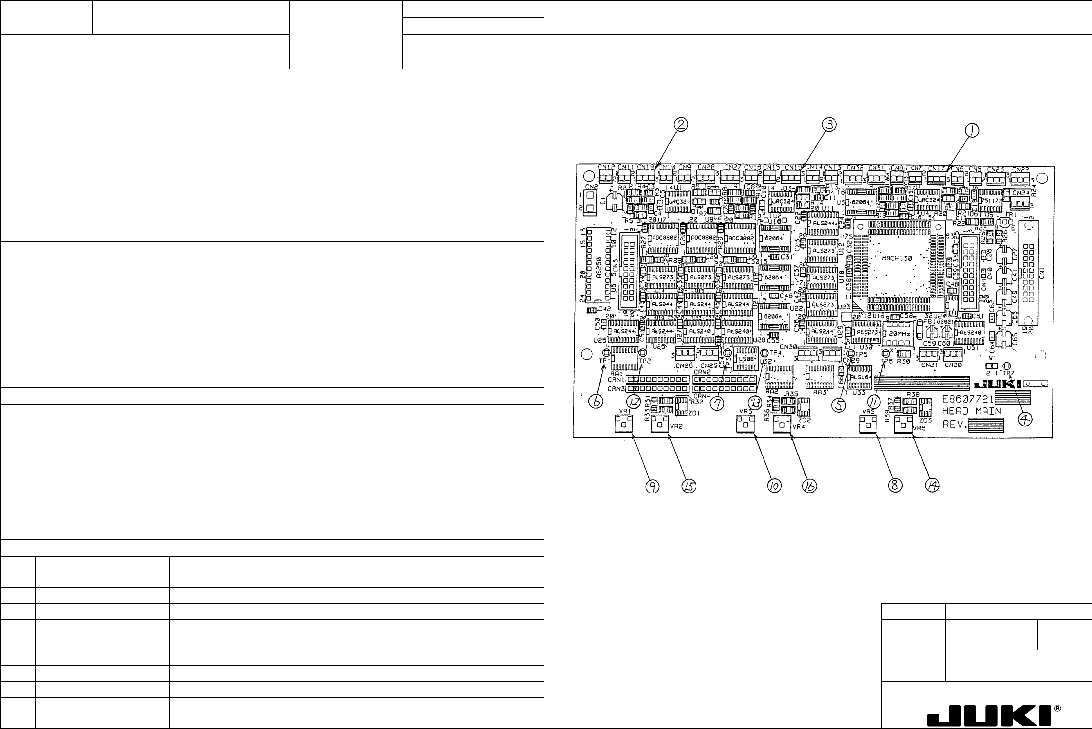
Locations of voltage measurement points and variable resistors
– DAC input voltage: Pressure sensor output voltage x 1/2
– DAC reference voltage: 1.25 V ±0.01 V
Serving as the adjustment of the nozzle vacuum measurement circuit, it is directly concerned with the measurement value of
vacuum.
1. Faulty vacuum value resulting in a pickup-and-placement motion error.
2. Reduced placement cycle time

MODEL KE-750/760
UNIT Electrical REF. NO.
NAME
EL-8
FUNCTION Head Vacuum Level 2/2
NAME
QA Table
Before starting the adjustment procedure, make sure that the DC power source voltage has been properly adjusted.
Adjustment procedure
a. Check that the pressure sensors have been connected to CN17, 18, and 19 of the head main board. (Connection to
CN19 is not necessary in KE-760.)
b. Close the circuit breaker and turn ON power.
c. With the sensors connected, measure the voltage of pin 2 of the following and record the values:
(1) CN17 Left head
(2) CN18 Right head
(3) CN19 Center head
(4) TP7 GND
d. Measure the voltage at the following check pins:
(5) TP5 Left head
(6) TP1 Right head
(7) TP3 Center head
(4) TP7 GND
Turn the following variable resistors so that the voltages measured become 1/2 of the measurements taken in step c:
(8) VR5 Left head
(9) VR1 Right head
(10) VR3 Center head
e. Turn the following variable resistors so that the voltages at the following check pins become 1.25 V ±0.01 V:
Check pins:
(11) TP6 Left head
(12) TP2 Right head
(13) TP4 Center head
(4) TP7 GND
Variable resistors:
(14) VR6 Left head
(15) VR2 Right head
(16) VR4 Center head
This completes the adjustment of the head vacuum level.
FUNCTION NAME OCC Light L Light Map Function/Performance CHECK/ADJUSTMENT METHODS (REMEDIAL ACTION PROCEDURE)
ASSURED QUALITY Reliability
QUALITY CHARACTERISTICS (SPECIFICATION VALUES) CATEGORY Safety
Product Image
ROLE IN FUNCTION (MEANING OF SPECIFICATION VALUES)
POSSIBLE MALFUNCTIONS (CAUSED BY INCORRECT SPECIFICATION VALUES)
COMPONENTS
NO. Part No. Part Name Associated Quality Characteristics
1 E86067250A0 Base unit board assembly DC power source output voltage adjustment
2 E86127210A0 OCC light board assembly
3 MODEL KE-750/760
4 UNIT Electrical REF. NO.
5
NAME
EL-9
6 FUNCTION OCC Light L Light Map
7
NAME
8
9
10
QA Table
1. Before making the adjustment, make sure that the DC power source output voltage has been properly adjusted.
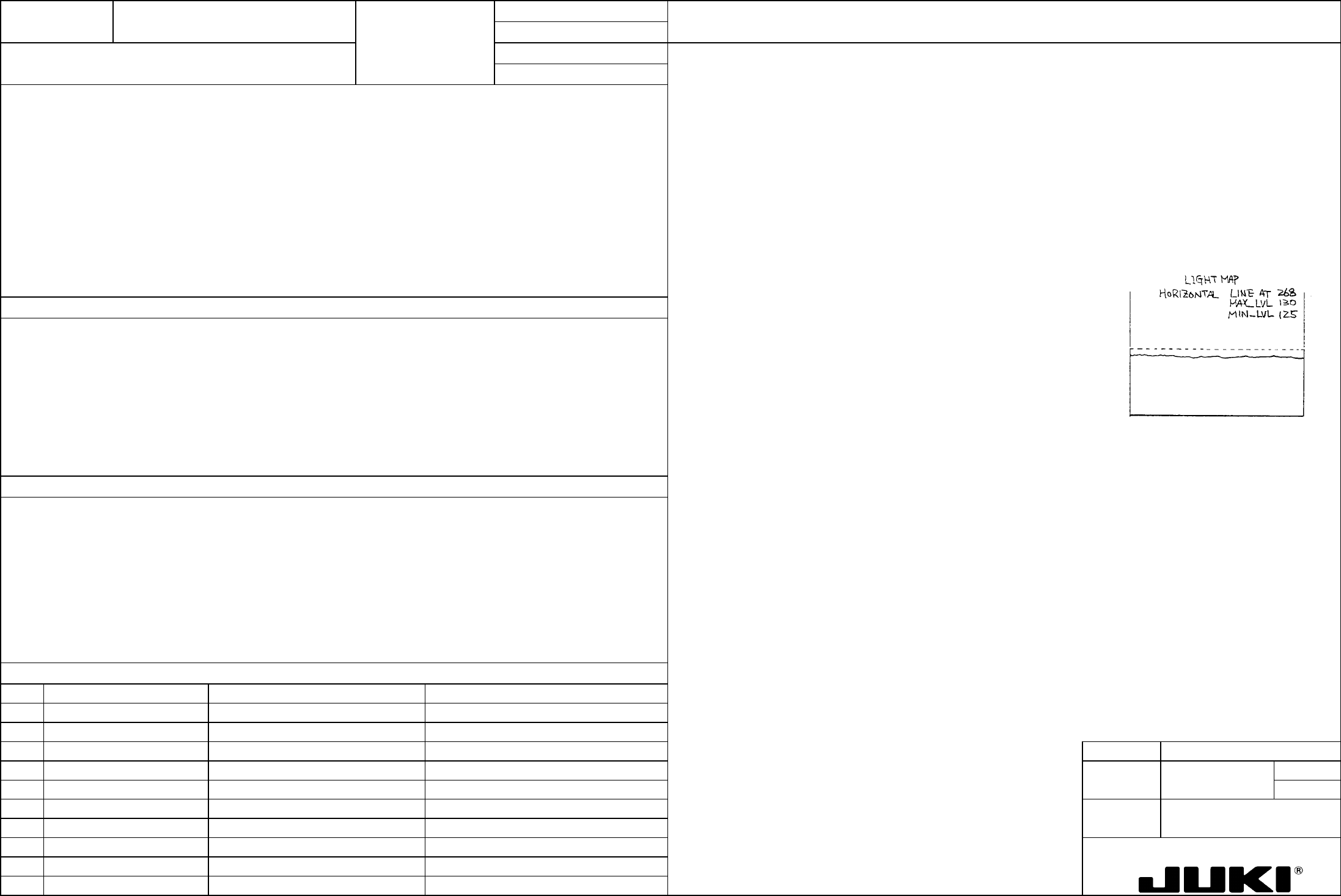
Light map MAX_LVL = 130 ±5
2. Turn ON the OCC light L.
3. With a white ceramic PWB clamped and positioned on the transport rails, move the head so that the OCC camera L can
view the center of the ceramic PWB.
4. Read the light map at the center in the horizontal direction and turn VR1 of the base unit board to obtain the specified
MAX_LVL value.
5. After VR1 has been adjusted, read light map several times to ensure that the map is stabilized.
Note: When adjusting the OCC light, turn the polarizer filter to a position that provides the brightest light map.
Serving as the adjustment of brightness of lighting for recognition of BOC mark and IC mark, it affects the image taken in
through the recognition process. It also affects the image reading of feed bank recognition.
1. Degraded placement accuracy
2. BOC mark and IC mark recognition error
3. Feeder bank mark recognition error
4. Error in the automatically calculated pickup position value for feeder bank position correction