KE-750_QA表.pdf - 第46页
FUNCTION NAME Clamping PWB in Vertical Di rection Function/Performanc e CHECK/ADJUSTMENT METHODS (REMEDIAL ACTION PROCEDURE) ASSURED QUALITY Reliability QUALITY CHARACTERISTI CS (SPECIFICATION VALUES) CATEGORY Safety Pro…
FUNCTION NAME Changing the Transport Rail Width Function/Performance CHECK/ADJUSTMENT METHODS (REMEDIAL ACTION PROCEDURE)
ASSURED QUALITY Reliability
QUALITY CHARACTERISTICS (SPECIFICATION VALUES) CATEGORY Safety
Product Image
ROLE IN FUNCTION (MEANING OF SPECIFICATION VALUES)
POSSIBLE MALFUNCTIONS (CAUSED BY INCORRECT SPECIFICATION VALUES)
COMPONENTS
NO. Part No. Part Name Associated Quality Characteristics
1 E2010725000 Screw shaft
2 E2009725000 Guide shaft
3 MODEL KE-750/760
4 UNIT Transport REF. NO.
5
NAME
16
6 FUNCTION Changing the Transport Rail
7
NAME Width
8
9
10
QA Table
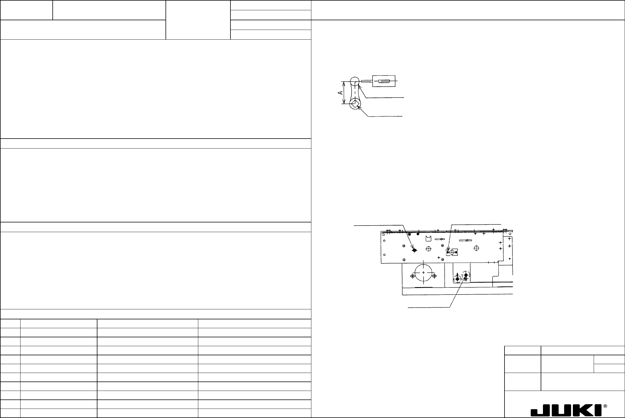
1. Apply a spring balance to the handle shaft knob and pull it in the tangential direction to measure torque in the handle shaft.
1. Handle shaft torque: 0.2 N.m or less
2. Drive belt tension: 2 to 2.5 kgf
Handle shaft axis
Handle shaft knob
Spring balance
Guide shaft parallelism adjustment:
At a 254-mm transport rail width position, fix the ball bushing position.
Loosen the screw on the end of guide shaft on the rail plate F side and tighten that screw at a 31-mm rail width position.
Screw shaft parallelism adjustment:
1. To ensure optimum torque of the PWB width adjusting handle shaft
Fix the nut position at a 254-mm PWB width position.
2. To ensure optimum tension in the timing belt that connects the right and left screw shafts
Loosen the screw on the adjust plate and tighten that screw at a 31-mm rail width position.
2. Drive belt tension
Adjust the tension by changing the height of the idler pulley. It, however, also changes the timing belt height; so be
careful about its contact with T-PIN sensor.
Take tension measurements using an acoustic wave type belt tensiometer (manufactured by Unitta).
Idler pulley set scre
w
A
djust plate set scre
w
Guide shaft end set scre
w
1. If the torque is too large, feel of operation of the rail width adjustment is not positive.
If the guide shaft and screw shaft do not run parallel, it could result in "narrow gap" and "galling" in the movable rail.
2. Tension too tight: The screw shaft flexes causing a heavy torque.
Tension too weak: Belt cogs are skipped at the pulley.
FUNCTION NAME Clamping PWB in Vertical Direction Function/Performance CHECK/ADJUSTMENT METHODS (REMEDIAL ACTION PROCEDURE)
ASSURED QUALITY Reliability
QUALITY CHARACTERISTICS (SPECIFICATION VALUES) CATEGORY Safety
Product Image
ROLE IN FUNCTION (MEANING OF SPECIFICATION VALUES)
POSSIBLE MALFUNCTIONS (CAUSED BY INCORRECT SPECIFICATION VALUES)
COMPONENTS
NO. Part No. Part Name Associated Quality Characteristics
1 E2010725000 Screw shaft
2 E2009725000 Guide shaft
3 MODEL KE-750/760
4 UNIT Transport REF. NO.
5
NAME
17
6 FUNCTION Clamping PWB in Vertical
7
NAME Direction
8
9
10
QA Table
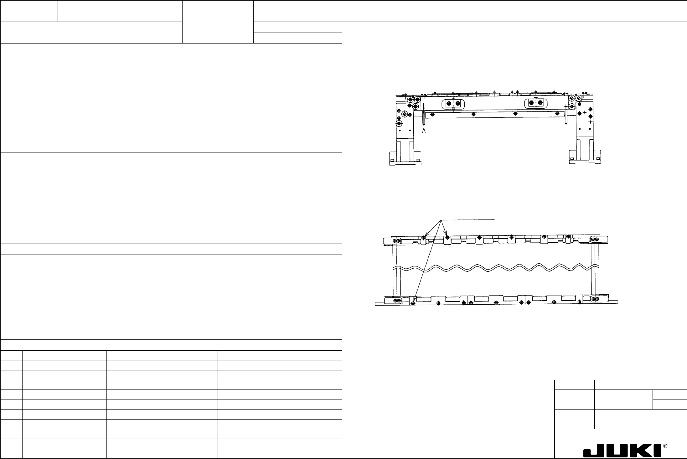
1. As the BU table moves up and down, the transport rail CF and CR move up and down smoothly.
Check procedure:
Check to see if the transport rails follow the up-and-down movement of the transport rails.
Push up the rail guide shaft with a finger to determine if the transport rails lightly move up.
PWB guide set screws
If the PWB guide interferes with the rails, loosen the screws shown
below and adjust.
Press with a finger.
1. To clamp the PWB smoothly in the vertical direction
1. Interference with the PWB guide prevents the transport rail from moving up.
The right and left shaft support assemblies do to run parallel with each other, causing the rails to bind.
A defective shaft support bearing causes the rails to bind.
FUNCTION NAME X/Y Belt Tension Function/Performance CHECK/ADJUSTMENT METHODS (REMEDIAL ACTION PROCEDURE)
ASSURED QUALITY Reliability
QUALITY CHARACTERISTICS (SPECIFICATION VALUES) CATEGORY Safety
Product Image
ROLE IN FUNCTION (MEANING OF SPECIFICATION VALUES)
POSSIBLE MALFUNCTIONS (CAUSED BY INCORRECT SPECIFICATION VALUES)
COMPONENTS
NO. Part No. Part Name Associated Quality Characteristics
1 E2431725000 Timing belt XA
2 E2432725000 Timing belt XB
3 E2306725000 Timing belt YA MODEL KE-750/760
4 E2308725000 Timing belt YB UNIT X-Y Unit REF. NO.
5
NAME
XY-1
6 FUNCTION X/Y Belt Tension
7
NAME
8
9
10
QA Table
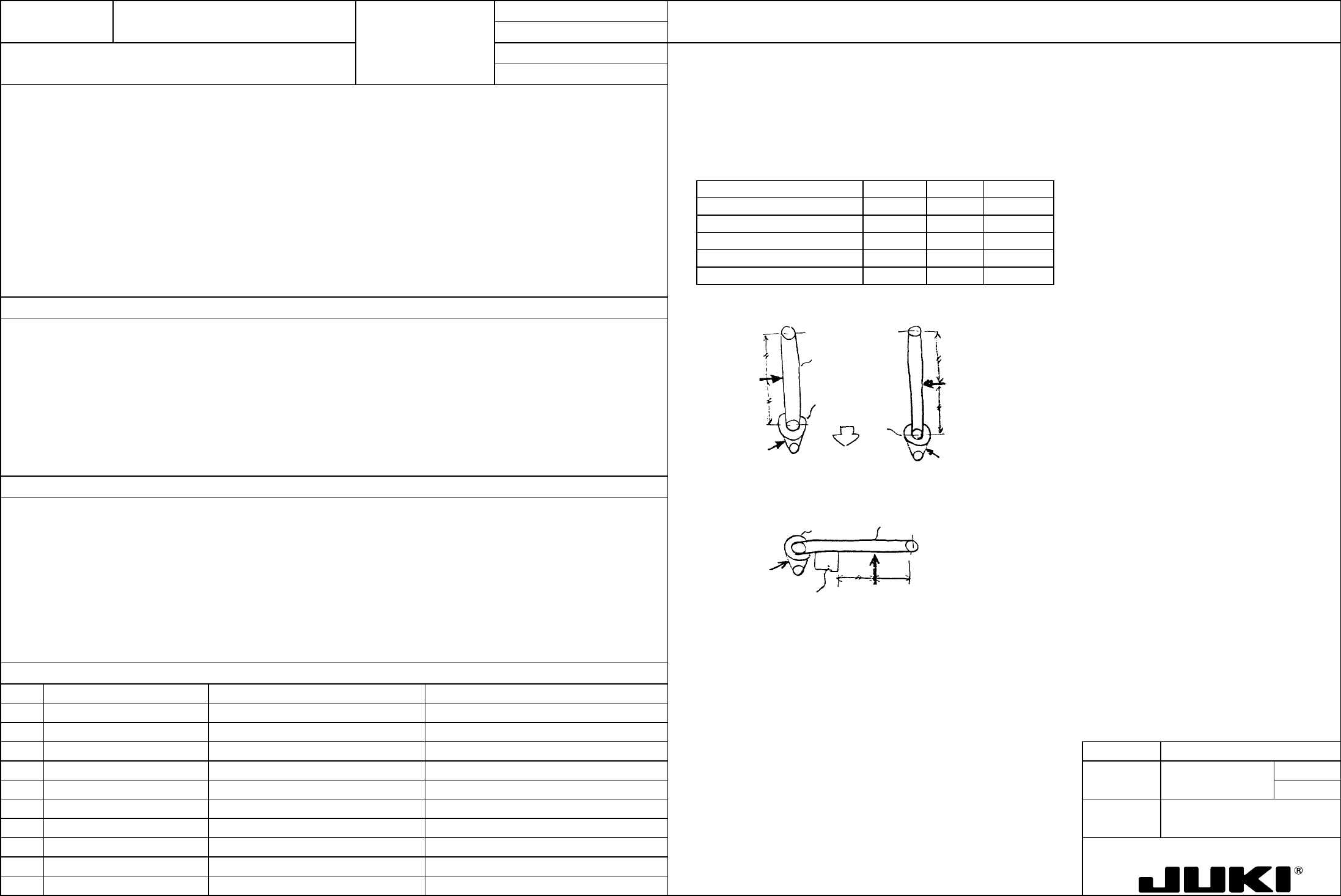
Check procedure:
X belt (timing belt XB) = 95±5 kgf
Apply the tensiometer ( ) manufactured by Unitta in the direction of the arrow in the illustration on the right to measure
the belt tension.
YL belt (timing belt YB) = 120±5 kgf
YR belt (timing belt YB) = 80±5 kgf
X motor belt (timing belt XA) = 18±5 kgf
Tensiometer input items
Y motor belt (timing belt YA) = 18±5 kgf
Belt Item Belt width Span Unit weight
X motor belt (timing belt XA) 20 118 0.13
Y motor belt (timing belt YA) 20 96.5 0.13
X belt (timing belt XB) 60 1154 0.38
YR belt (timing belt YB) 60 980 0.38
YL belt (timing belt YB) 60 980 0.38
Left-end limit for
head
Measure
Measure
[Y-axis]
X belt
X motor belt
[X-axis]
Front end limit
for X-axis
Measure
Measure
Measure
Measure
Y motor
belt
YR belt
Y motor belt
YL belt
Directly concerned with the settling time (damping characteristics) at the placement and pickup positions, it greatly affects the
placement accuracy.
1. Degraded placement accuracy
2. Pickup failure resulting in a standing chip and laser error
3. Hunting at stopping
4. Abnormal oscillation during operation
5. Degraded stopping accuracy