KE-750_QA表.pdf - 第63页
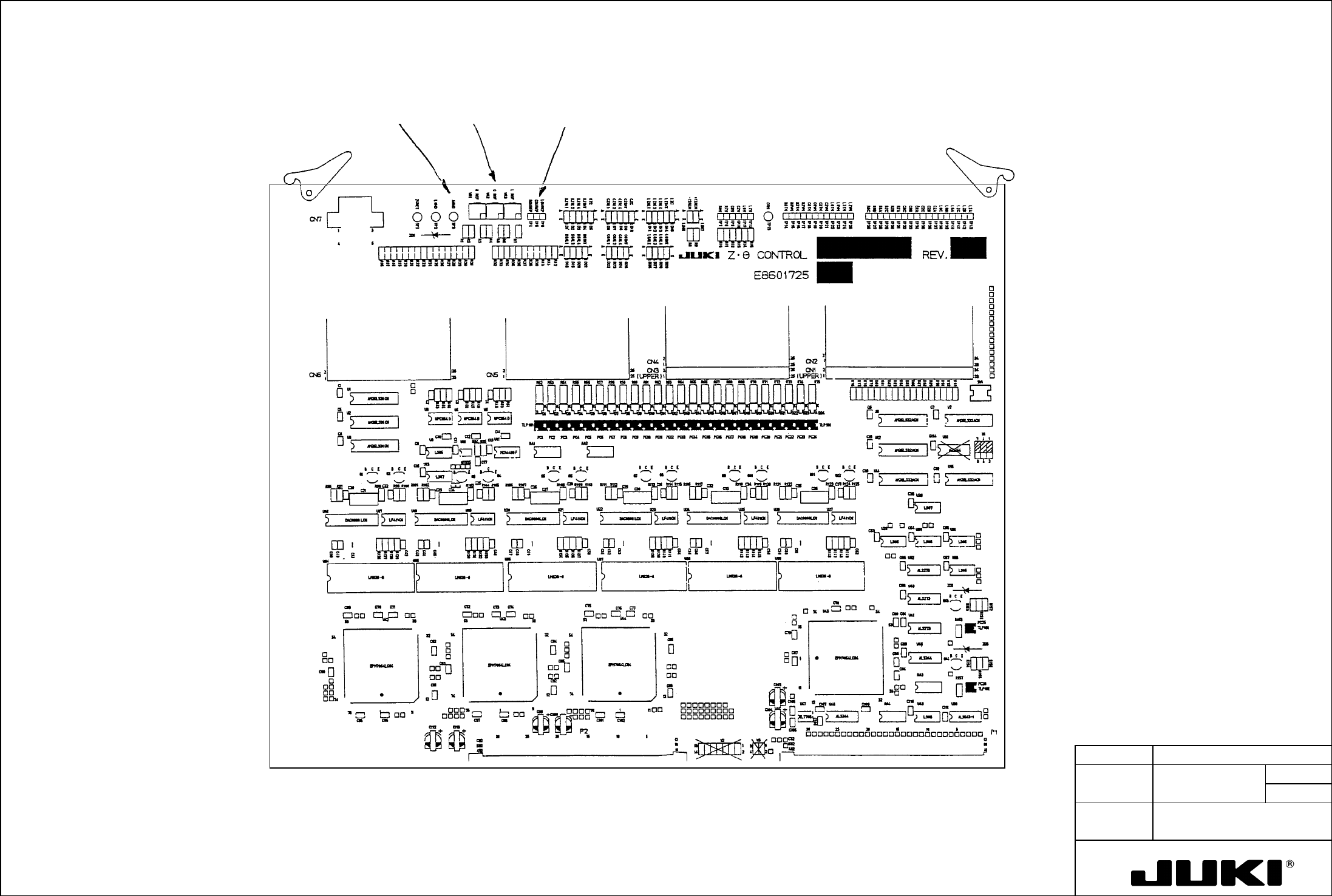
MODEL KE-750/760 UNIT Electrical REF. NO. NAME EL-3 FUNCTION Z θ Control Board D/A Reference NAME Voltage 2/2 QA Table VR1, 2, 3 Layout of Check Pins and Variable Resistor TP3 TP4, 5, 6
FUNCTION NAME Zθ Control Board D/A Reference Voltage Function/Performance CHECK/ADJUSTMENT METHODS (REMEDIAL ACTION PROCEDURE)
ASSURED QUALITY Reliability
QUALITY CHARACTERISTICS (SPECIFICATION VALUES) CATEGORY Safety
Product Image
ROLE IN FUNCTION (MEANING OF SPECIFICATION VALUES)
POSSIBLE MALFUNCTIONS (CAUSED BY INCORRECT SPECIFICATION VALUES)
COMPONENTS
NO. Part No. Part Name Associated Quality Characteristics
1 E86017250A0 Zθ control board assembly DC power source output voltage adjustment
2 E8601725AA0 Zθ control board A assembly
3 MODEL KE-750/760
4 UNIT Electrical REF. NO.
5
NAME
EL-3
6 FUNCTION Zθ Control Board D/A Reference
7
NAME Voltage 1/2
8
9
10
QA Table
1. Before attempting to start adjusting the D/A reference voltage, ensure that the DC power source output voltage has been
properly adjusted.
5.0V ± 0.01V
LDAREF
CDAREF
2. Using a digital voltmeter, measure the voltage at the check pins [TP6 (LDAREF), TP5 (CDAREF), TP4 (RDAREF)]. Use
TP3 (AGND) for the ground pin. (E8601725OAO is only on TP5.)
RDAREF
3. Turn variable resistors [VR3 (LREF), VR2 (CREF), VR1 (RREF) as necessary to make the measurements taken fall within
the specifications.
Here is a list of correspondence between the check pins and variable resistors.
TP6 LDAREF VR3 LREF
TP5 CDAREF VR2 CREF
TP4 RDAREF VR1 RREF
Directly concerned with the operation of Z-axis and $-axis motors of the head, it greatly affects placement accuracy.
1. Degraded placement accuracy
2. Laser error
3. ATC nozzle change error
4. Oscillation at stopping
5. Servo driver alarm
MODEL KE-750/760
UNIT Electrical REF. NO.
NAME
EL-3
FUNCTION Zθ Control Board D/A Reference
NAME Voltage 2/2
QA Table
VR1, 2, 3
Layout of Check Pins and Variable Resistor
TP3
TP4, 5, 6
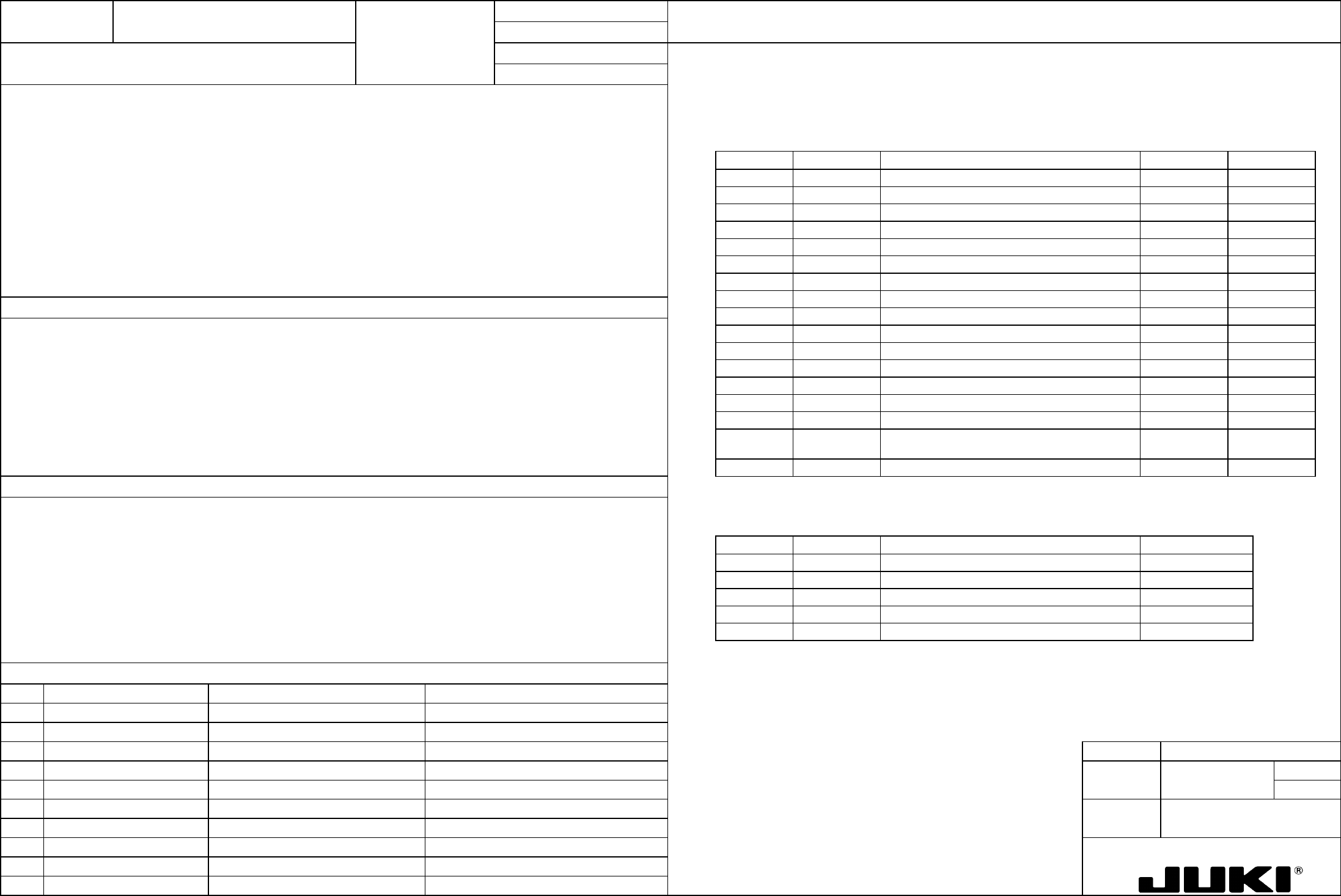
FUNCTION NAME Z-Axis/θ-Axis Servo Driver Parameters Function/Performance CHECK/ADJUSTMENT METHODS (REMEDIAL ACTION PROCEDURE)
ASSURED QUALITY Reliability
QUALITY CHARACTERISTICS (SPECIFICATION VALUES) CATEGORY Safety
Product Image
ROLE IN FUNCTION (MEANING OF SPECIFICATION VALUES)
POSSIBLE MALFUNCTIONS (CAUSED BY INCORRECT SPECIFICATION VALUES)
COMPONENTS
NO. Part No. Part Name Associated Quality Characteristics
1 KM000000070 30-W AC servo multi-axis unit (4-axis)
2 KM000000080 30-W AC servo multi-axis unit (2-axis)
3 MODEL KE-750/760
4 UNIT Electrical REF. NO.
5
NAME
EL-4
6 FUNCTION Z-Axis/θ-Axis Servo Driver
7
NAME Parameters 1/8
8
9
10
QA Table
Setting values
See the adjustment procedure that follows.
Parameters in screen mode 0
See p. 2/8 and onward for the setting procedure.
Page no. Abbreviation Name Z-axis
θ-axis
0 Kp Position loop gain — —
1 Kff Feed forward gain — —
2 Kvp Speed loop proportional gain 100 50
3 Tvi Speed loop integral time constant 20 10
4 INP Positioning completion signal width — —
5 OVF Excessive deviation value — —
6 EGER Electronic gear ratio — —
7 ENCR Output pulse dividing ratio 1/2 1/1
8 LTG Low speed 50 50
9 PMOD Command pulse train configuration — —
Serves as the control parameters of Z/$-axis, directly affecting the operation of Z/$-axis.
10 SSW1 Selector switch 1 00000000 00000000
11 SSW2 Selector switch 2 00000001 00000000
12 VLPF Speed command LPF 500 500
13 ILPF Current command LPF 500 500
14 Tacc Speed command acceleration/deceleration time 0 0
15 Tpcm Position command acceleration/deceleration time
constant
— —
16 Scal Speed scale 2000 4000
Parameters in screen mode 1
1. Degraded placement accuracy
2. Pickup failure, standing chip error
Page no. Abbreviation Name
Common to Z/θ-axis
3. ATC nozzle change error
0 TYPE Control mode Velocity
4. Oscillation at stopping
1 ENKD Encoder type INC.E
5. Servo driver alarm
2 ENPL No. of encoder pulses 2000 P/R
3 MOT Motor type P50B03003P
4 CABLE Applicable cable length 0 - -5m
A dash "-" in the setting value column indicates that the parameter is not used, requiring no setting.