KE-750_QA表.pdf - 第47页
FUNCTION NAME X/Y Belt Tension Function/Performance CHECK/ADJUSTMENT METHODS (REMEDIAL ACTION PROCEDURE) ASSURED QUALITY Reliability QUALITY CHARACTERISTI CS (SPECIFIC ATION VALUES) CATEGORY Safety Product Image ROLE IN …
FUNCTION NAME Clamping PWB in Vertical Direction Function/Performance CHECK/ADJUSTMENT METHODS (REMEDIAL ACTION PROCEDURE)
ASSURED QUALITY Reliability
QUALITY CHARACTERISTICS (SPECIFICATION VALUES) CATEGORY Safety
Product Image
ROLE IN FUNCTION (MEANING OF SPECIFICATION VALUES)
POSSIBLE MALFUNCTIONS (CAUSED BY INCORRECT SPECIFICATION VALUES)
COMPONENTS
NO. Part No. Part Name Associated Quality Characteristics
1 E2010725000 Screw shaft
2 E2009725000 Guide shaft
3 MODEL KE-750/760
4 UNIT Transport REF. NO.
5
NAME
17
6 FUNCTION Clamping PWB in Vertical
7
NAME Direction
8
9
10
QA Table
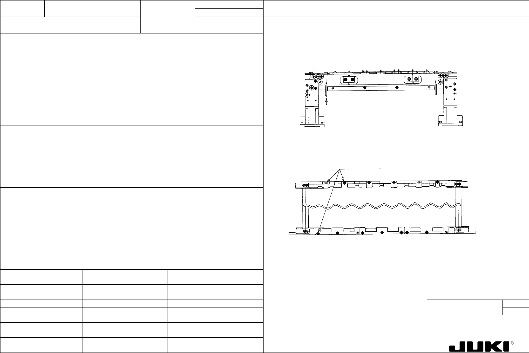
1. As the BU table moves up and down, the transport rail CF and CR move up and down smoothly.
Check procedure:
Check to see if the transport rails follow the up-and-down movement of the transport rails.
Push up the rail guide shaft with a finger to determine if the transport rails lightly move up.
PWB guide set screws
If the PWB guide interferes with the rails, loosen the screws shown
below and adjust.
Press with a finger.
1. To clamp the PWB smoothly in the vertical direction
1. Interference with the PWB guide prevents the transport rail from moving up.
The right and left shaft support assemblies do to run parallel with each other, causing the rails to bind.
A defective shaft support bearing causes the rails to bind.
FUNCTION NAME X/Y Belt Tension Function/Performance CHECK/ADJUSTMENT METHODS (REMEDIAL ACTION PROCEDURE)
ASSURED QUALITY Reliability
QUALITY CHARACTERISTICS (SPECIFICATION VALUES) CATEGORY Safety
Product Image
ROLE IN FUNCTION (MEANING OF SPECIFICATION VALUES)
POSSIBLE MALFUNCTIONS (CAUSED BY INCORRECT SPECIFICATION VALUES)
COMPONENTS
NO. Part No. Part Name Associated Quality Characteristics
1 E2431725000 Timing belt XA
2 E2432725000 Timing belt XB
3 E2306725000 Timing belt YA MODEL KE-750/760
4 E2308725000 Timing belt YB UNIT X-Y Unit REF. NO.
5
NAME
XY-1
6 FUNCTION X/Y Belt Tension
7
NAME
8
9
10
QA Table
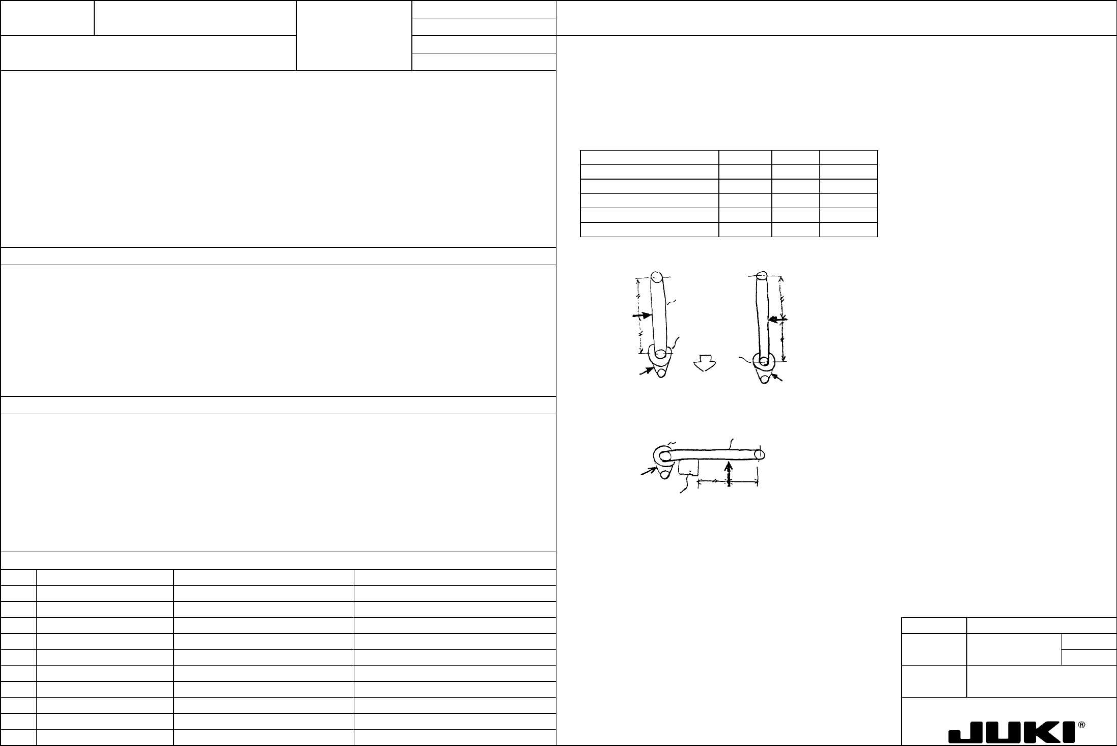
Check procedure:
X belt (timing belt XB) = 95±5 kgf
Apply the tensiometer ( ) manufactured by Unitta in the direction of the arrow in the illustration on the right to measure
the belt tension.
YL belt (timing belt YB) = 120±5 kgf
YR belt (timing belt YB) = 80±5 kgf
X motor belt (timing belt XA) = 18±5 kgf
Tensiometer input items
Y motor belt (timing belt YA) = 18±5 kgf
Belt Item Belt width Span Unit weight
X motor belt (timing belt XA) 20 118 0.13
Y motor belt (timing belt YA) 20 96.5 0.13
X belt (timing belt XB) 60 1154 0.38
YR belt (timing belt YB) 60 980 0.38
YL belt (timing belt YB) 60 980 0.38
Left-end limit for
head
Measure
Measure
[Y-axis]
X belt
X motor belt
[X-axis]
Front end limit
for X-axis
Measure
Measure
Measure
Measure
Y motor
belt
YR belt
Y motor belt
YL belt
Directly concerned with the settling time (damping characteristics) at the placement and pickup positions, it greatly affects the
placement accuracy.
1. Degraded placement accuracy
2. Pickup failure resulting in a standing chip and laser error
3. Hunting at stopping
4. Abnormal oscillation during operation
5. Degraded stopping accuracy
MODEL KE-750/760
UNIT X-Y Unit REF. NO.
NAME
XY-1
FUNCTION X/Y Belt Tension 2/2
NAME
QA Table
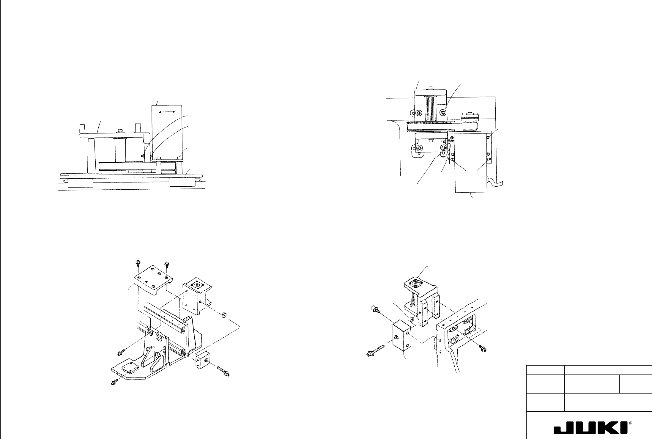
Adjustment procedure * Timing belt YA
(1) Loosen SL6061642TN that secures the YM bracket assembly.
* Timing belt XA (2) Loosen lock nut 6050001SC and turn SM8053002TP as necessary to adjust tension.
(3) After the adjustment has been made, tighten SL6061642TN to 15 Nm.
(1) Loosen SL6051492TN that secures the XM bracket assembly. (4) Tighten lock nut NM6050001SC.
(2) Loosen lock nut NM6050001SC and turn SM8053002TP as necessary to adjust tension.
SM8053002TP
NM6050001SC
YM bracket assembl
y
Straight
pins
SL6061642TN
(tightening torque 15 Nm)
YA pulley bracket assembl
y
(3) After the adjustment has been made, tighten SL6051492TN to 9 Nm.
(4) Tighten lock nut NM6050001SC.
SL6051492TN
SM8053002TP
NM6050001SC
X frame end L
XM bracket assembl
y
XA pulley bracket
assembly
* Timing belt XB
* Timing belt YB
(1) Loosen SL6061692TN that secures the XB pulley bracket assembly.
(1) Loosen SL6062592TN that secures the YB pulley bracket L and R assemblies.
(2) Loosen lock nut NM6060001SC and turn SL6065092TN as necessary to adjust tension.
(2) Loosen lock nut NM6060001SC and turn SL6065092TN as necessary to adjust tension.
(3) After the adjustment has been made, tighten SL6061692TN to 15 Nm.
(3) After the adjustment has been made, tighten SL6062592TN to 15 Nm.
(4) Tighten lock nut NM6060001SC.
(4) Tighten lock nut NM6060001SC.
XB pulley bracket assembl
y
NM6060001SC
SL6065092TN
E2407725000
X tension support
SL6061692TN
(tightening torque 15 Nm)
XB suppor
t
E2419725000
SL6065092TN
NM6060001SC
SL6062592TN
(tightening torque
15 Nm)
Y tension suppor
t
E2315725000
YB pulley bracket
L/R assembly