KE-750_QA表.pdf - 第76页
MODEL KE-750/760 UNIT Electrical REF. NO. NAME EL-7 FUNCTION PWB Detection Sensor NAME Sensitivity 2/2 QA Table Output and Indicator Lamp Operation Chart 2. Sensitivity adjustment 7.0X o r more 6.0X o r more 5.0X o r mor…
FUNCTION NAME PWB Detection Sensor Sensitivity Function/Performance CHECK/ADJUSTMENT METHODS (REMEDIAL ACTION PROCEDURE)
ASSURED QUALITY Reliability
QUALITY CHARACTERISTICS (SPECIFICATION VALUES) CATEGORY Safety
Product Image
ROLE IN FUNCTION (MEANING OF SPECIFICATION VALUES)
POSSIBLE MALFUNCTIONS (CAUSED BY INCORRECT SPECIFICATION VALUES)
COMPONENTS
NO. Part No. Part Name Associated Quality Characteristics
1 E94637250A0 IN sensor cable assembly
2 E94657250A0 STOP sensor cable assembly
3 E94667250A0 C.OUT sensor cable assembly MODEL KE-750/760
4 E94677250A0 OUT sensor cable assembly UNIT Electrical REF. NO.
5 E94647250A0 WAIT sensor cable assembly
NAME
EL-7
6 FUNCTION PWB Detection Sensor
7
NAME Sensitivity 1/2
8
9
10
QA Table
Adjustment of reflector type sensors
The sensor shall be capable of detecting black glass epoxy PWBs with no gloss (no resist) and glass epoxy PWBs with green
resist on bottom surfaces and with no resist on R surfaces.
1. Turn the sensitivity adjustment knob of the sensor to the MIN position.
2. Place a black glass epoxy PWB with no gloss (no resist) on the transport rails above the sensor.
3. Slowly turn the sensitivity adjustment knob of the sensor clockwise from the MIN position and stop turning it when the
indicator lamp lights up.
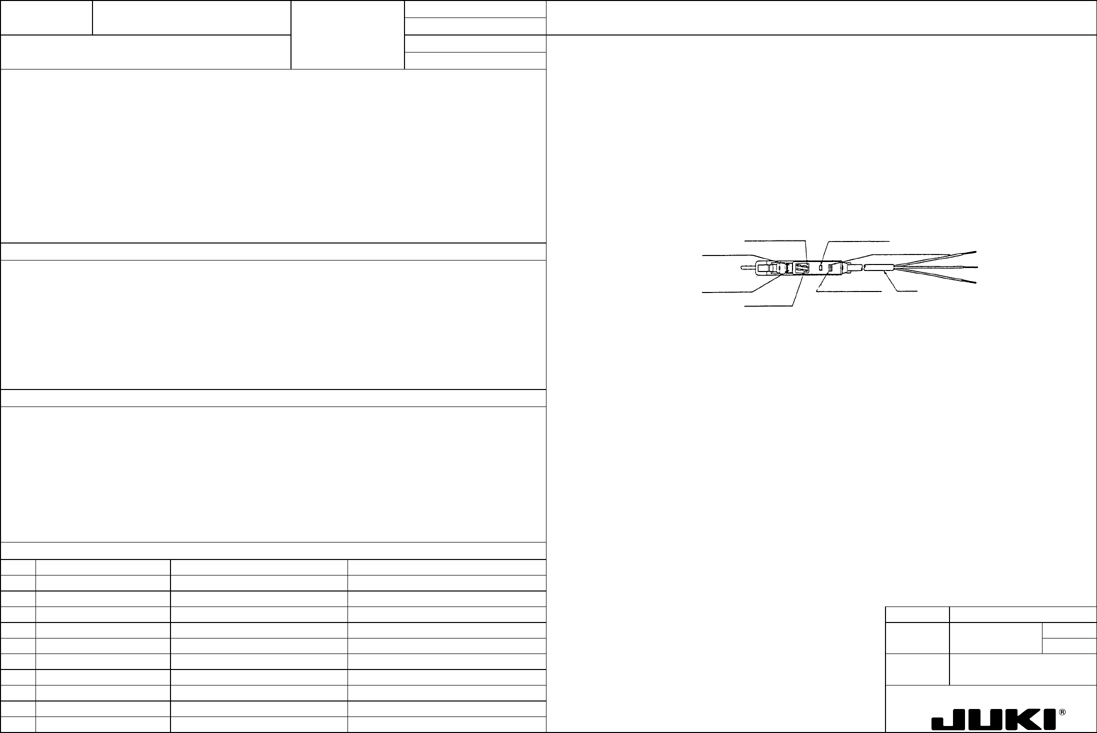
Adjustment of interrupter type sensor (WAIT sensor amplifier)
1. Switch setting
Place the L-ON/D-ON selector switch in the D-ON position.
Tuning button
L-ON/D-ON selector switch
Cord
Mode selector switch
Digital displa
y
Operation indicator lamp (red)
Stability indicator lamp (green)
Off delay indicator lamp
This adjustment ensures that the sensor detects PWBs of various colors and does not sense any object including the safety
cover other than PWBs.
1. PWB detection error while PWBs are being transported.
MODEL KE-750/760
UNIT Electrical REF. NO.
NAME
EL-7
FUNCTION PWB Detection Sensor
NAME Sensitivity 2/2
QA Table
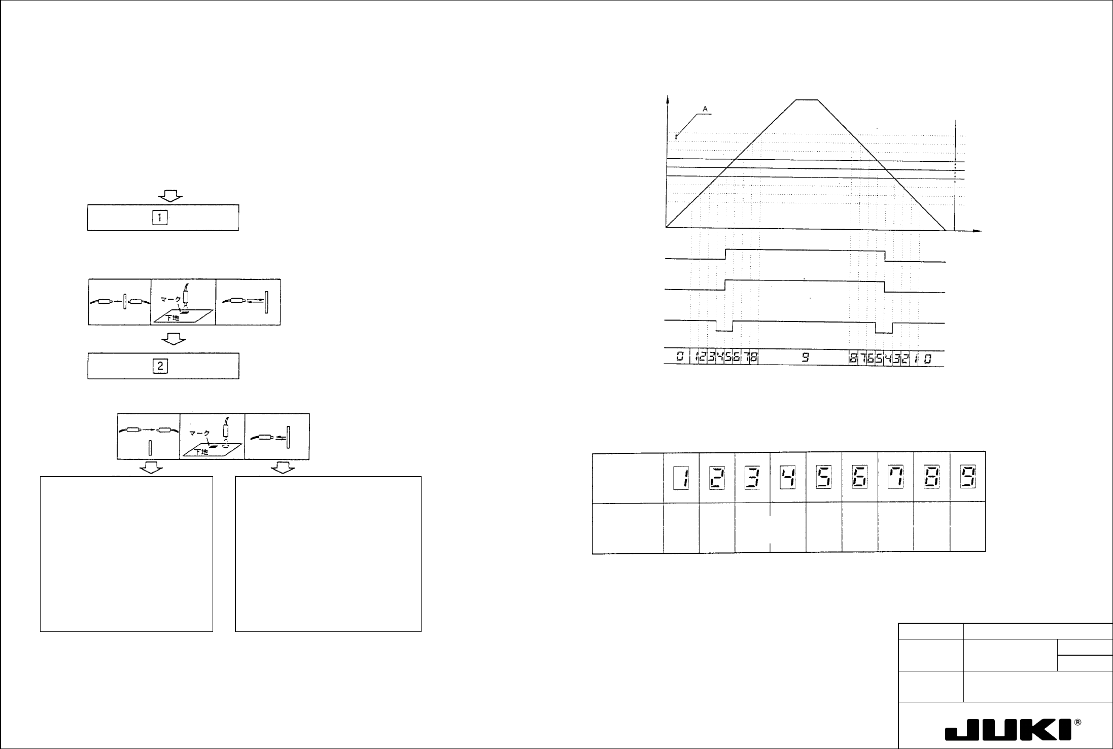
Output and Indicator Lamp Operation Chart
2. Sensitivity adjustment
7.0X o
r
more
6.0X o
r
more
5.0X o
r
more
4.0X o
r
more
3.0X o
r
more
2.0X o
r
more
1.5X o
r
more
1.2X o
r
more
1.0X o
r
more
Margin
(magnification) with
respect to
hysteresis
automatically set
Detection
margin display
(digital
display)
Detection Margin Displa
y
Here is a guideline for detection margin display that is given in digital form at the end of
sensitivity setting.
A
: Twice as large as the amount of hysteresis automatically set at
sensitivity setting
Striking ligh
t
intensity level
display (digital)
Stabilization
indicator lamp
(green)
Control output (L-
ON setting)
Operation indicato
r
lamp (red) (L-ON
setting)
Time
Stabilized light blocking
Unstable amount of light striking
Unstable light blocking
Stabilized amoun
t
o
f
ligh
t
striking
Operation level
A
mount o
f
incident light
[1] For the adjustment, use as the workpiece a glass epoxy PWB with green resist on the F surface and with no resist on
R surface.
[2] Place the mode selector switch in the SET position. (If the switch is placed back in the RUN position at this time, a
change of sensitivity setting will not be valid.)
Digital display ... [1] (standby for 1st run)
Indicator lamp (red): OFF
Indicator lamp (green): OFF
Indicator lamp (red): OFF
Indicator lamp (green): Blinking
Digital display (standby for 2nd
[3] Place the workpiece at the specified place and press the tuning button. (1st run) (See Note 1 below.)
If the sensitivity is lower than required:
Indicator lamp (red): Blinking
Digital display (2tandby for 2nd
Indicator lamp (green): Blinking
[4] Move the workpiece out and press the tuning button. (2nd run) (See Note 1 below.)
When tuning has been good:
When tuning has been unsuccessful:
Digital display ... Shows the detection
margin [1] to [9]
Digital display
... Low sensitivity error [E] blinking
Low level difference error [E] ON
Place the mode selector switch in the
RUN position. This completes the
sensitivity setting.
Change the workpiece position and setting
distance and press the tuning button again.
*If the sensor is to be retuned, keep the
mode selector switch in the SET position
and press the tuning button once again.
The digital display shows "1" again, allowing
you to perform steps from [2] to [4].
The digital display shows "1" again,
allowing you to perform steps from [2] to
[4].
Digital display ... [1] (standby for 1st run)
Digital display ... [1] (standby for 1st run)
*If the mode selector switch is placed in the
RUN position in incorrect tuning condition,
the error display remains and the amplifier
does not operate.
Note 1: The same sensitivity setting can be made even if the workpiece conditions are exchanged between steps [3] and
[4].
FUNCTION NAME Head Vacuum Level Function/Performance CHECK/ADJUSTMENT METHODS (REMEDIAL ACTION PROCEDURE)
ASSURED QUALITY Reliability
QUALITY CHARACTERISTICS (SPECIFICATION VALUES) CATEGORY Safety
Product Image
ROLE IN FUNCTION (MEANING OF SPECIFICATION VALUES)
POSSIBLE MALFUNCTIONS (CAUSED BY INCORRECT SPECIFICATION VALUES)
COMPONENTS
NO. Part No. Part Name Associated Quality Characteristics
1 E86077210A0 Head main board assembly DC power source output voltage adjustment
2 E93157250A0 Head 1 pressure sensor assembly
3 E93187250A0 Head 2 pressure sensor assembly MODEL KE-750/760
4 E93217250A0 Head 3 pressure sensor assembly UNIT Electrical REF. NO.
5
NAME
EL-8
6 FUNCTION Head Vacuum Level 1/2
7
NAME
8
9
10
QA Table
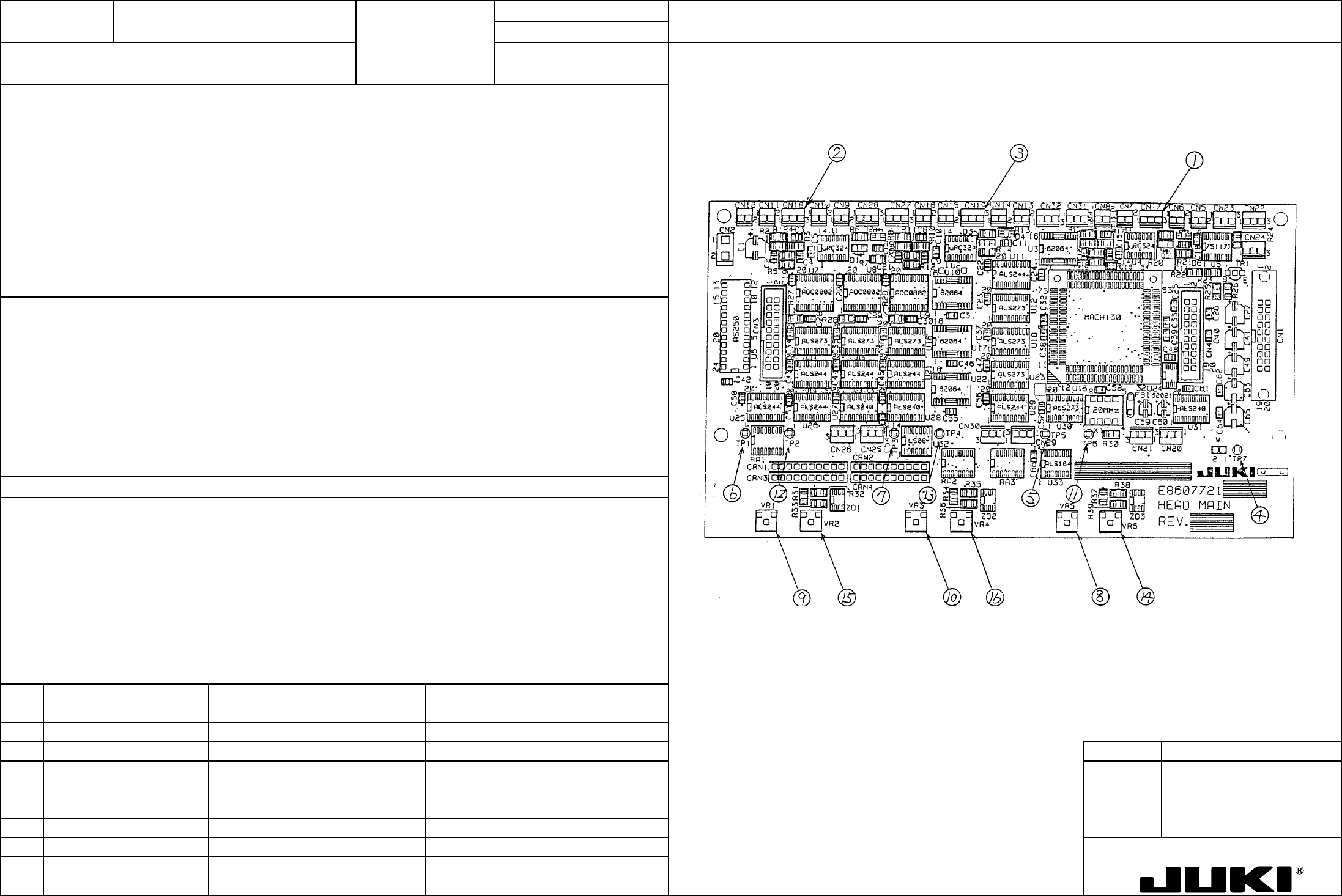
Locations of voltage measurement points and variable resistors
– DAC input voltage: Pressure sensor output voltage x 1/2
– DAC reference voltage: 1.25 V ±0.01 V
Serving as the adjustment of the nozzle vacuum measurement circuit, it is directly concerned with the measurement value of
vacuum.
1. Faulty vacuum value resulting in a pickup-and-placement motion error.
2. Reduced placement cycle time