OM-1683-001_w.pdf - 第35页
18 OM-1683 10. "MOTOR" Window This window enables you to perform a manual operation (inching) of each unit and view the current system information. Reference Refer to "6.2 "MOTOR" W indow" i…
17
OM-1683
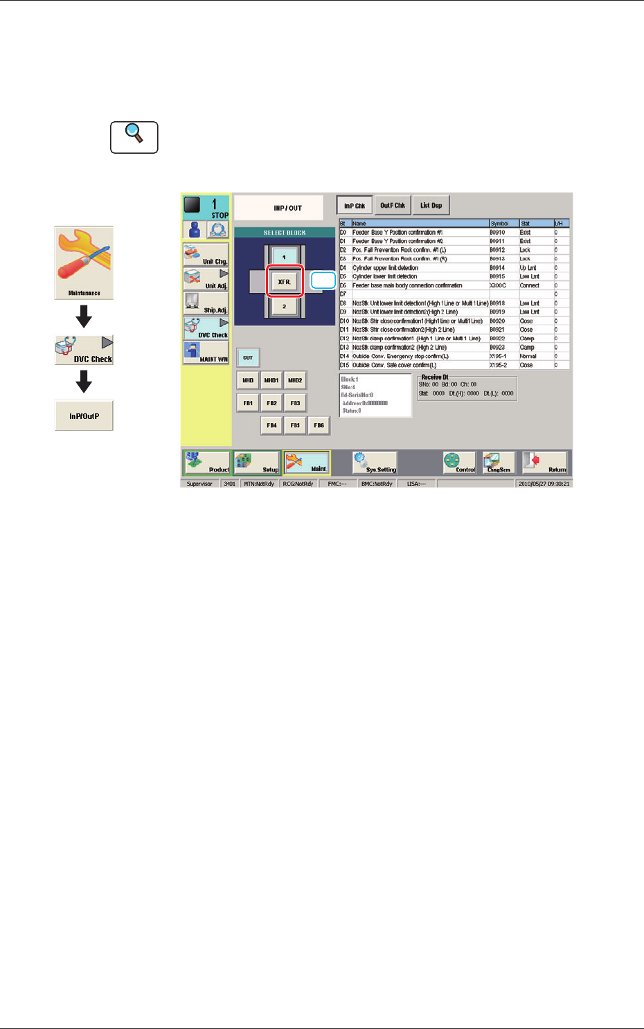
9. "INP/OUT" Window
This window enables the operator to conrm the input/output status for the
PCB transfer.
Reference
Refer to "6.1 "INP/OUT" Window" in Chapter 1, Volume 3, in the
SIGMA-G5 main machine instruction manual for the information other
than for dual transfer.
[1]
Fig. 17 INP/OUT
[1] [XFR.] Button
When pressed the conrmation of the input/output status for the PCB transfer
is available.
Graphic
Development
1103-001
9. "INP/OUT" Window
18
OM-1683
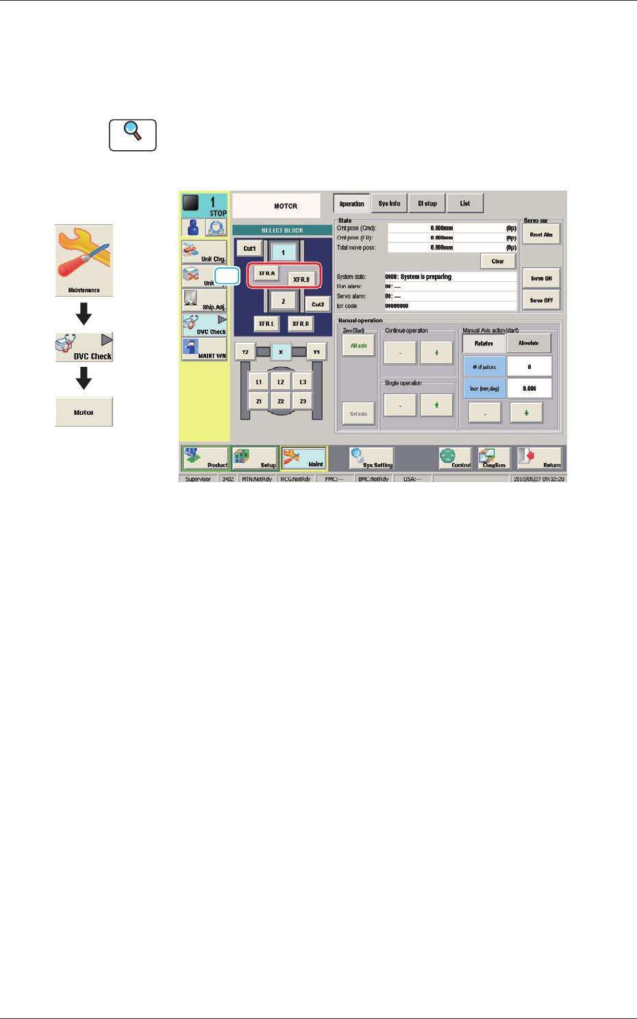
10. "MOTOR" Window
This window enables you to perform a manual operation (inching) of each
unit and view the current system information.
Reference
Refer to "6.2 "MOTOR" Window" in Chapter 1, Volume 3, in the
SIGMA-G5 main machine instruction manual for the information other
than for dual transfer.
[1]
Fig. 18 MOTOR
[1] [XFR. A, B] Button
When pressed, the conrmation of the transfer unit for each corresponding
transfer lane, is available.
Graphic
Development
1103-001
10. "MOTOR" Window
19
OM-1683
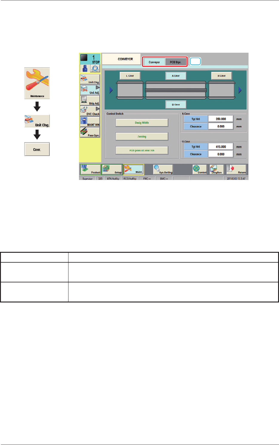
11. "CONVEYOR" Window
This button is used for the adjustment operation for the conveyor width overall
setup.
[1]
Fig. 19 CONVEYOR
[1] Tabs
The "CONVEYOR" Window is provided with the following two tabs.
When cach tab is pressed, the corresponding tab sheet appears.
Table 1
Tabs Description
Conveyor
When this tab is selected the tab sheet for the conveyor operation is displayed.
PCB Stpr.
When this tab is selected the tab sheet for the PCB stopper operation is
displayed.
1103-001
11. CONVEYOR
Graphic
Development