OM-1683-001_w.pdf - 第74页
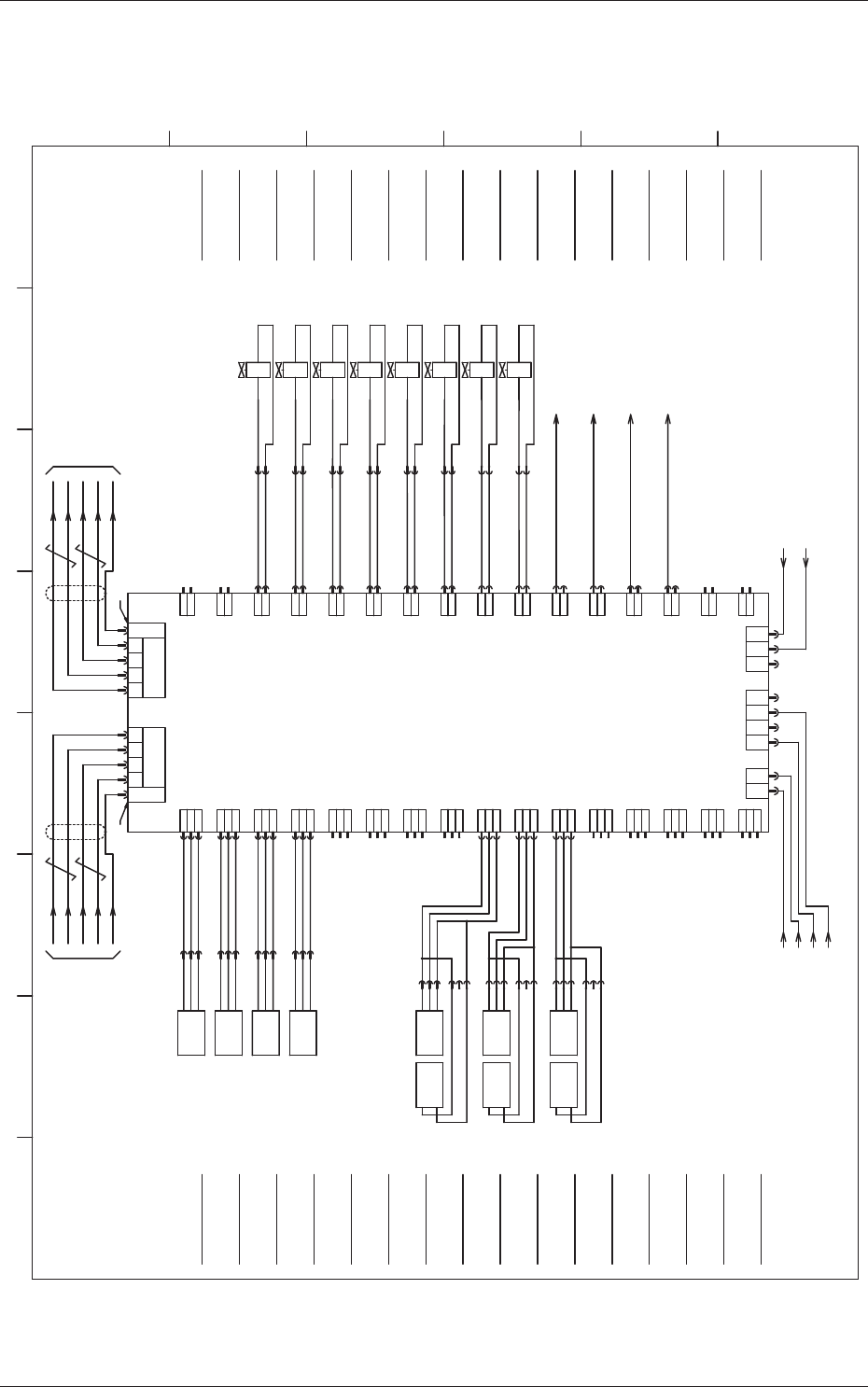
57 OM-1683 15.4 Circuit Diagram 24B1 10B 10A 24A3 1 2 3 3 2 1 3 2 1 3 2 1 3 2 1 3 2 1 1 2 3 1 2 3 1 2 3 1 2 3 1 2 3 3 2 1 3 2 1 3 2 1 3 2 1 3 2 1 2 1 1 2 1 2 1 2 1 2 1 2 1 2 1 2 1 2 1 2 1 2 1 2 1 2 1 2 1 2 1 2 X1411 X141…
56
OM-1683
15.4 Circuit Diagram
X0801 X0802
IN OUT
CN10
1 2
3
CN4
CN3
21
24B1
10B
10A
24A3
CN11
CN12
CN13
CN14
CN15
CN16
CN17
CN18
CN19
CN20
CN21
CN22
CN23
CN25
1
2
3
3
2
1
3
2
1
3
2
1
3
2
1
3
2
1
1
2
3
1
2
3
1
2
3
1
2
3
1
2
3
3
2
1
3
2
1
3
2
1
3
2
1
3
2
1
2
1
CN45
CN43
CN42
CN41
CN40
CN39
CN38
CN37
CN36
CN35
CN34
CN33
CN32
CN31
CN30
CN24
1
2
1
2
1
2
1
2
1
2
1
2
1
2
1
2
1
2
1
2
1
2
1
2
1
2
1
2
1
2
CN44
4
X0820
X0811
X0810
X0832
X0833
X0836
X0837
X0803 X0804
716
707
706
724
725
728
729
X0842
734
733
X0841
X0840
732
RX
/RX
TX
/TX
7 39 5 5 93 7
/TX
TX
/RX
RX
[NE/13/3D] [NE/13/3E]
[NE/13/3C]
[NE/13/3C]
STLT_CNVR(L)
I/O P.C.B
U08
X0839
731
708
709
X0843
735
B0810
XB0810
:3
+
OUT
-
:2
:1
B0820
+
OUT
-
B0820T
-
+
XB0820
:3
:2
:1
:6
:5
:4
X0812
X0813
B0811
XB0811
:3
+
OUT
-
:2
:1
B0812
XB0812
:3
+
OUT
-
:2
:1
B0813
XB0813
:3
+
OUT
-
:2
:1
Y0832
:1
:2
XY0832
BK R
Y0833
:1
:2
XY0833
BK R
Y0836
:1
:2
XY0836
BK R
Y0837
:1
:2
XY0837
BK R
Y0839
:1
:2
XY0839
BK R
[NE/03/2B]
[NE/03/2D]
[NE/03/2C]
[NE/03/2E]
B0819
+
OUT
-
B0819T
-
+
XB0819
:3
:2
:1
:6
:5
:4
B0818
+
OUT
-
B0818T
-
+
XB0818
:3
:2
:1
:6
:5
:4
X0819
X0818
X0835
X0838
727
730
X0834
726
Y0834
:1
:2
XY0834
BK R
Y0835
:1
:2
XY0835
BK R
Y0838
:1
:2
XY0838
BK R
715
714
CN1A CN2A
1 2
3
CN26
X0826
548
24A3
[NE/13/3C]
to X27163:3
U27(RLY)
[NE/13/3C]
ch1-1
(U12:X1202)
HLS-LINK HLS-LINK
(-X1300F1(Rear))
ch1-1
1 2 3 4 5 6 7 8
A
B
C
D
E
F
Movable 3L
Z Clamp Cylinder Valve
(A:Descent)
Movable 3L
Z Clamp Cylinder Valve
(B:Ascent)
Movable 1,2L
Z Clamp Cylinder Valve
(A:Descent)
Movable 1,2L
Z Clamp Cylinder Valve
(B:Ascent)
(Option)
PCB Positioning Stopper 5
Up/Down Valve (NA)
(Option)
PCB Positioning Stopper 6
Up/Down Valve (NA)
PCB Stopper AL
PCB Stopper BL
Stop Sensor B Mounting
Section 1 Remote / L Flow
Stop Sensor B Mounting
Section 2 Remote / R Flow
Stop Sensor B Mounting
Section 2 Remote / L Flow
Stop Sensor B Mounting
Section 1 Remote / R Flow
(Opttion)
Stop Sensor B Mounting
Section 3 Remote (OP) / L Flow
(Opttion)
Stop Sensor B Mounting
Section 4 Remote (OP) / R Flow
to B4701:5
Stop Sensor B Mounting Section 1 Remote
to B4801:5
Stop Sensor B Mounting Section 2 Remote
to B4702:5
Stop Sensor B Mounting Section 3 Remote
to B4802:5
Stop Sensor B Mounting Section 4 Remote
Note 1 Note 1
FG
(Connector Case)
FG
(Connector Case)
(Option)
M121 Alarm Signal
(Option)
M122 Alarm Signal
Movable Chute
Backup Pin Sensor 3
(Light Reception / Light Emission)
Movable Chute
Backup Pin Sensor 2
(Light Reception / Light Emission)
Movable Chute
Backup Pin Sensor 1
(Light Reception / Light Emission)
PCB Stpper 5 Upper Sensor (OP) / L Flow
PCB Stpper AR Upper Sensor/ R Flow
PCB Stpper 6 Origin Sensor (OP) / L Flow
PCB Stpper BR Origin Sensor/ R Flow
PCB Stpper 6 Upper Sensor (OP) / L Flow
PCB Stpper BR Upper Sensor/ R Flow
PCB Stpper 5 Origin Sensor (OP) / L Flow
PCB Stpper AR Origin Sensor/ R Flow
1103-001B (M917WNE--0011)
U08 I/O P.C.B. STLT CNVR (L)
57
OM-1683
15.4 Circuit Diagram
24B1
10B
10A
24A3
1
2
3
3
2
1
3
2
1
3
2
1
3
2
1
3
2
1
1
2
3
1
2
3
1
2
3
1
2
3
1
2
3
3
2
1
3
2
1
3
2
1
3
2
1
3
2
1
2
1
1
2
1
2
1
2
1
2
1
2
1
2
1
2
1
2
1
2
1
2
1
2
1
2
1
2
1
2
1
2
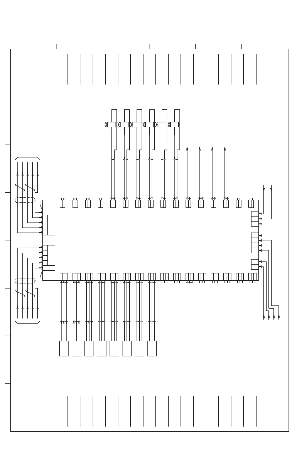
X1411
X1410
X1435
X1438
739
738
759
762
X1442
766
765
X1441
X1440
764
RX
/RX
TX
/TX
7 39 5 5 93 7
/TX
TX
/RX
RX
[NE/13/7D] [NE/13/7E]
[NE/13/7C]
[NE/13/7C]
STRT_CNVR(R)
I/O P.C.B
U14
X1434
758
740
741
X1443
767
B1410
XB1410
:3
+
OUT
-
:2
:1
X1412
X1413
B1411
XB1411
:3
+
OUT
-
:2
:1
B1412
XB1412
:3
+
OUT
-
:2
:1
B1413
XB1413
:3
+
OUT
-
:2
:1
Y1434
:1
:2
XY1434
BK R
Y1435
:1
:2
XY1435
BK R
Y1438
:1
:2
XY1438
BK R
[NE/06/2B]
[NE/06/2D]
[NE/06/2C]
[NE/06/2E]
X1416
X1415
X1414
744
743
742
745
X1417
B1414
XB1414
:3
+
OUT
-
:2
:1
B1415
XB1415
:3
+
OUT
-
:2
:1
B1416
XB1416
:3
+
OUT
-
:2
:1
B1417
XB1417
:3
+
OUT
-
:2
:1
X1436
X1437
760
761
X1439
763
Y1436
:1
:2
XY1436
BK R
Y1437
:1
:2
XY1437
BK R
Y1439
:1
:2
XY1439
BK R
X1401 X1402
IN OUT
CN10
CN11
CN12
CN13
CN14
CN15
CN16
CN17
CN18
CN19
CN20
CN21
CN22
CN23
CN25 CN45
CN43
CN42
CN41
CN40
CN39
CN38
CN37
CN36
CN35
CN34
CN33
CN32
CN31
CN30
CN24 CN44
CN1A CN2A
1 2 3
CN4
CN3
21 4
X1403 X1404
1 2 3
CN26
X1426
549
24A3
[NE/13/7C]
to X27163:4
U27(RLY)
[NE/13/7C]
ch2-1
(U06:X0602)
HLS-LINK HLS-LINK
(-X1300F1(Front))
ch2-1
1 2 3 4 5 6 7 8
A
B
C
D
E
F
Movable 3R
Z Clamp Cylinder Valve
(A:Descent)
Movable 3R
Z Clamp Cylinder Valve
(B:Ascent)
Movable 1,2R
Z Clamp Cylinder Valve
(A:Descent)
Movable 1,2R
Z Clamp Cylinder Valve
(B:Ascent)
PCB Stopper AR
PCB Stopper BR
Stop Sensor A Mounting
Section 1 Remote / L Flow
Stop Sensor A Mounting
Section 2 Remote / R Flow
Stop Sensor A Mounting
Section 2 Remote / L Flow
Stop Sensor A Mounting
Section 1 Remote / R Flow
(Opttion)
Stop Sensor A Mounting
Section 3 Remote (OP) / L Flow
(Opttion)
Stop Sensor A Mounting
Section 4 Remote (OP) / R Flow
to B4301:5
Stop Sensor A Mounting Section 1 Remote
to B4401:5
Stop Sensor A Mounting Section 2 Remote
to B4302:5
Stop Sensor A Mounting Section 3 Remote
to B4402:5
Stop Sensor A Mounting Section 4 Remote
Note 1 Note 1
FG
(Connector Case)
FG
(Connector Case)
(Option)
M123 Alarm Signal
(Option)
M124 Alarm Signal
PCB Stpper 5 Upper Sensor (OP) / L Flow
PCB Stpper AR Upper Sensor/ R Flow
PCB Stpper 6 Origin Sensor (OP) / L Flow
PCB Stpper BR Origin Sensor/ R Flow
PCB Stpper 6 Upper Sensor (OP) / L Flow
PCB Stpper BR Upper Sensor/ R Flow
PCB Stpper 5 Origin Sensor (OP) / L Flow
PCB Stpper AR Origin Sensor/ R Flow
PCB Stpper AL Origin Sensor
PCB Stpper AL Upper Sensor
PCB Stpper BL Origin Sensor
PCB Stpper BL Upper Sensor
1103-001B (M917WNE--0012)
U08 I/O P.C.B. STLT CNVR (R)
58
OM-1683
1103-001-(02002-1)
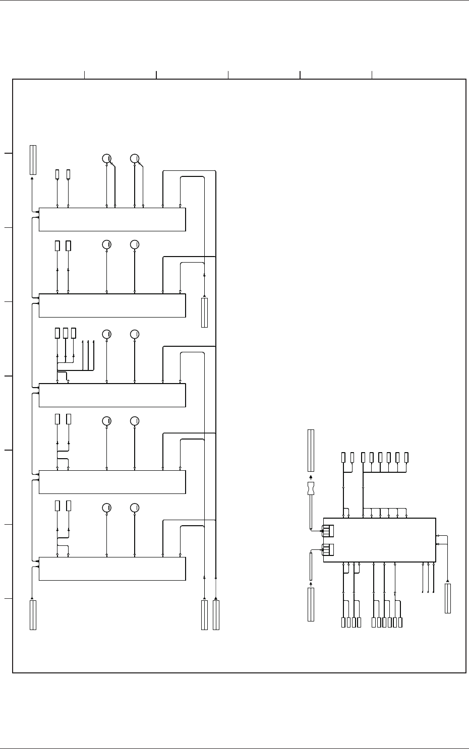
15.5 Cable Connection Diagram
M
M
M
M
M
M
M
M
M
M
1091401300-08
BA Side Panel
TB:DC1
1091401300-08
BA Side Panel
TB:DC1
UB77:X2762
1091401300-09
CPU2(U85) X8513
AE-LINK
Converter
U181(R)
2091401304-02
2091401304-02
X0804
X0803
BA Side Panel
TB:DC1
1091401300-08
X0801 X0802
HLS Collective Section
(U12):X1202
Bank Feeder Change Cart Connector Section (R)
X1300F1
1091401300-11
2091401304-02
A161A45 A47
X14106
X16108
CN8
Movable Chute 3 Origin Sensor
B16103
B16301
M163
NA-W3
CN8
CN4
M45
NL-LB1
M46
NL-LB2
CN8
CN4
M47
NA-LB1
M48
NA-LB2
A53
Backup 1 Origin
B5301
X5304
CN4
Backup 2 Origin
B5401
X5308
CN8
M53
NA-BAL
M54
NA-BAR
CN5
X16105
CN1
X4501
CN5
X4505
CN1
X4701
CN5
X4705
CN1
X5301
CN5
X5305
X4510
CN10
X4710
CN10
X16110
CN10
X15306
X5310
CN10
N1 N2 N1 N2 N1 N2 N1 N2
X4509
CN9
X4709
CN9
X16109
CN9
X5309
CN9
X12762
X4504
X4508
CN3
X5303
CN7
X5307
A41
CN8
CN4
CN1
X4101
CN5
X4105
X4110
CN10
N1 N2
X4109
CN9
X4104
X4108
Lane A Deceleration Sensor
Lane A Stop Sensor
B4102
B4101
B4102
B4101
M41
NL-LA1
M42
NL-LA2
X16104
CN4
Movable Chute 1 Origin Sensor
B16101
B16101
Lane B Deceleration Sensor
Lane B Stop Sensor
B4502
B4501
B4502
B4501
M161
NA-W1
CN1
X16101
CN2A/2BCN1A/1B
/RX
RX
/TX
TX
9,10
7,8
5,6
3,4
/RX
RX
/TX
TX
9,10
7,8
5,6
3,4
U08
Transfer L (UB32)
X0820
CN20
B0820
B0820
Movable Chute 3
PCB Support Pin Detection
B0820T
X0833
CN33
X0837
X0836
CN36
CN37
X0839
CN39
Y0836
Y0837
Movable 3 Z Clamp Down: L
Movable 3 Z Clamp Up: L
Y0839
PCB Stopper Lane B: L
CN4
CN3
X0812
CN12
B0812,0813
X0813
CN13
Y0833
PCB Stopper 6 (OP)
L
X0810
CN10
B0810,0811
X0811
CN11
X0819
CN19
B0819
B0819
Movable Chute 2
PCB Support Pin Detection 2
B0819T
X0818
CN18
B0818
B0818
Movable Chute 1
PCB Support Pin Detection 1
B0818T
X0832
CN32
X0835
X0834
CN34
CN35
X0838
CN38
Y0834
Y0835
Movable 1.2 Z Clamp Down: L
Movable 1.2 Z Clamp Up: L
Y0838
PCB Stopper Lane A: L
Y0832
PCB Stopper 5 (OP)
B0810
B0811
PCB Stopper Origin : OP5
PCB Stopper Upper : OP5
B0812
B0813
PCB Stopper Origin : OP6
PCB Stopper Upper : OP6
X4704
X4708
Lane B Stop Sensor A Mounting Section 1
B4702
B4701
B4702
B4701
Lane B Stop Sensor A Mounting Section 3
X0840
X0841
B4801
B4801
Lane B Stop Sensor A Mounting Section 2
X0842
X0840
CN40
X0841
CN41
B4701
B4801
X0842
CN42
B4702
1 2 3 4 5 6 7 8
A
B
C
D
E
15.5 Cable Connection Diagram
Dual Transfer Harness Connection Diagram 1