YC8_Ope_E.pdf - 第38页
1-3 1 Part names and functions n Signal light Indicates current operating conditions of the mounter with a green, yello w and red light, or green, white and blue light explained below . (T he color of the signal light wh…
1-2
1
Part names and functions
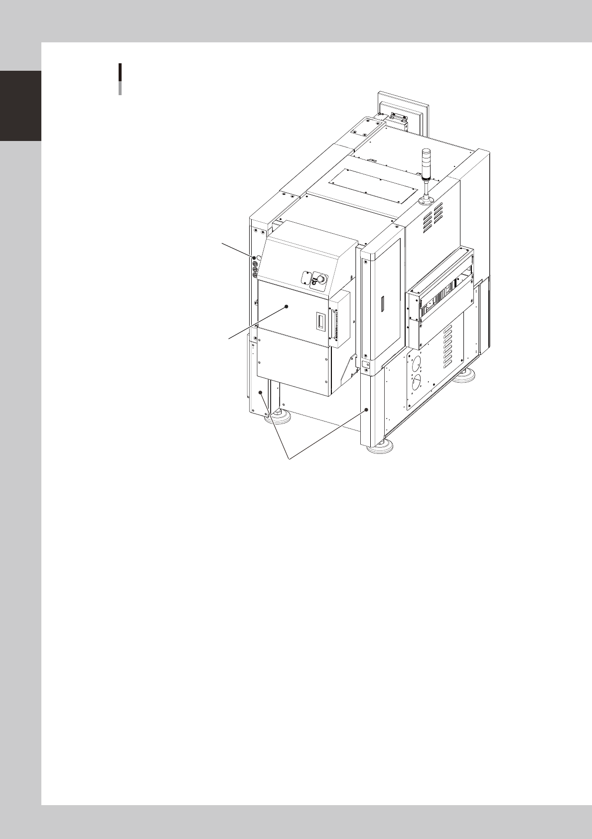
Machine main unit
Rear view
Machine-to-machine interface connector
(Behind lower left cover and lower right cover)
Operation panel buttons (option)
ATS15 (option)
23101-N8-00
1-3
1
Part names and functions
n
Signal light
Indicates current operating conditions of the mounter with a green, yellow and red light, or green, white and blue light
explained below. (The color of the signal light when a buzzer sounds can be selected from two patterns (option).)
Machine status Example Green
Red/
White
Yellow/
Blue
Warm-up or automatic operation ON ----- -----
Emergency stop ----- ON -----
System error
(with buzzer ON)
• Excessive current
• Secondary limit over
----- ON -----
Operation or board data error
(with buzzer ON)
• Pickup error, recognition error
• Data check error, etc.
----- ----- ON
Components cannot be used. • Components run out. ----- ----- Flashing
n
Alarm buzzer
This buzzer sounds if an error or abnormal operation occurs. (The color of the signal light when a buzzer sounds can be
selected from two patterns (option). (The buzzer volume can be adjusted by turning the buzzer ring right or left.)
n
Safety cover
This cover must be closed during operation. If opened, emergency stop is triggered.
n
Pressure gauge
Shows the supply air pressure (upper display) and pressure-drop detection level (lower display). Use the pressure
regulator knob and the pressure-drop detection level adjust buttons on the pressure gauge to set each pressure value as
follows:
• Supply air pressure (upper display) : 0.40 MPa
• Pressure-drop detection level (lower display) : 0.33 MPa
n
Head assembly
Picks up and mounts components with the nozzles at the tip. The head assembly also has two cameras: one for scanning
and recognizing components and the other for recognizing marks on boards. (See "3. Head assembly" in this chapter.)
n
Behind front lower left panel
An air supply/shutoff switch and USB ports are located.
n
Power switch
Turns on or off the power to the machine. The power is on when turned to the right.
c
Wait about 2 seconds before turning the power switch back on after turning it off.
n
Feeder setup section
Mainly tape feeders are installed here. (See "4.1 Supplying components from feeder plates" for details.
n
Tape reel holder (option)
This is installed in front of the feeder set section and holds tape reels in place.
n
Connection between machines (input/output signals between machines)
The mounter ejects the finished board when it receives a signal from the machine in the next process, and then sends a
signal to the machine in the preceding process to request another board. The interface connector labeled "NEXT
INTERFACE" connects to the machine in the next process, and the interface connector labeled "PREVIOUS INTERFACE"
connects to the machine in the preceding process.
In the case of standard machines of right-to-left flow, the PREVIOUS INTERFACE connector is located behind the rear
right cover of the machine, and the NEXT INTERFACE connector behind the rear left cover.
1-4
1
Part names and functions
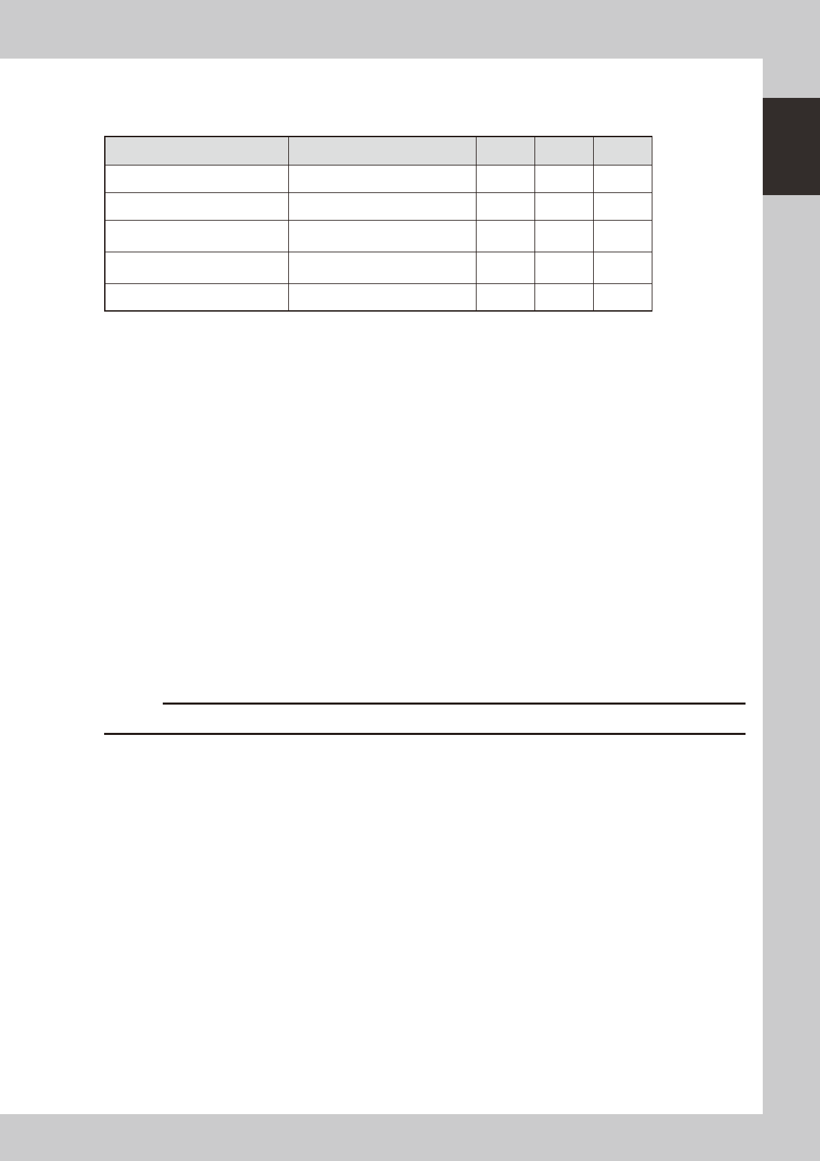
2. Operation panel and data input unit
Standard machines are equipped with an operation display, operation panel buttons, a keyboard and a
mouse on the front and rear (option) of the machine, to operate the machine and make data settings. The
functions of these units are explained below.
Mouse
Operation panel and data input unit
Operation display
(touch screen is optional)
Operation panel button
Keyboard
23102-N8-00
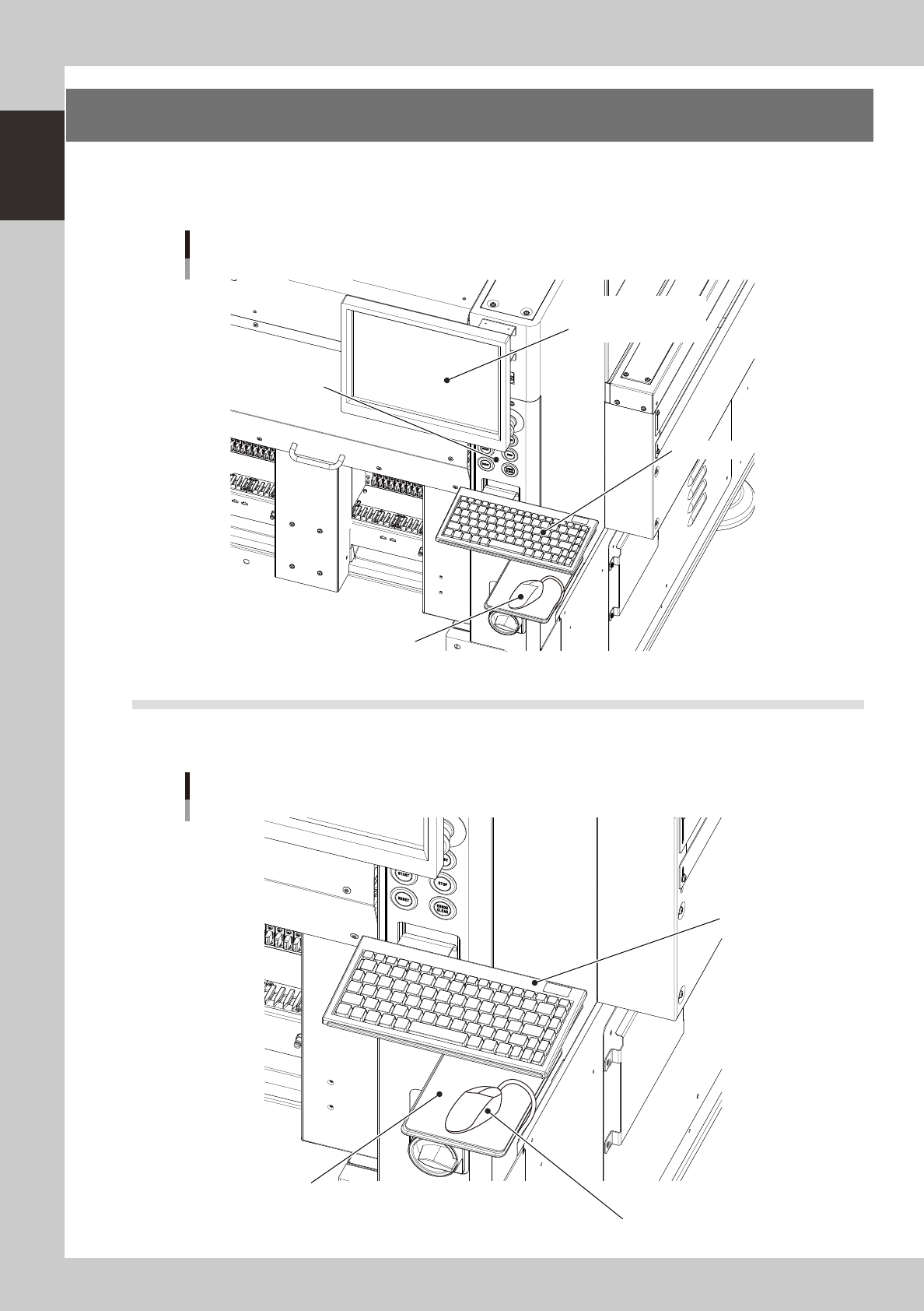
2.1 Keyboard and mouse
This machine is equipped with a keyboard and mouse as standard features to operate the machine or edit data
settings. To select a menu button or parameter item on the operation screen, click it with the left mouse button.
Keyboard and mouse
Mouse
Mouse pad
Keyboard
23103-N8-00