YC8_Ope_E.pdf - 第42页
1-7 1 Part names and functions 3.2 Nozzle types T o ensure stable component pickup, the correct nozzle that matches the component must be used. T he following sections explain typical nozzles w hich can be attac hed to e…
1-6
1
Part names and functions
3. Head assembly
The head assembly is mounted on the XY arms and moves to pick up and place components. This section
describes the head assembly configurations and nozzle types.
3.1 Component pick-and-place head
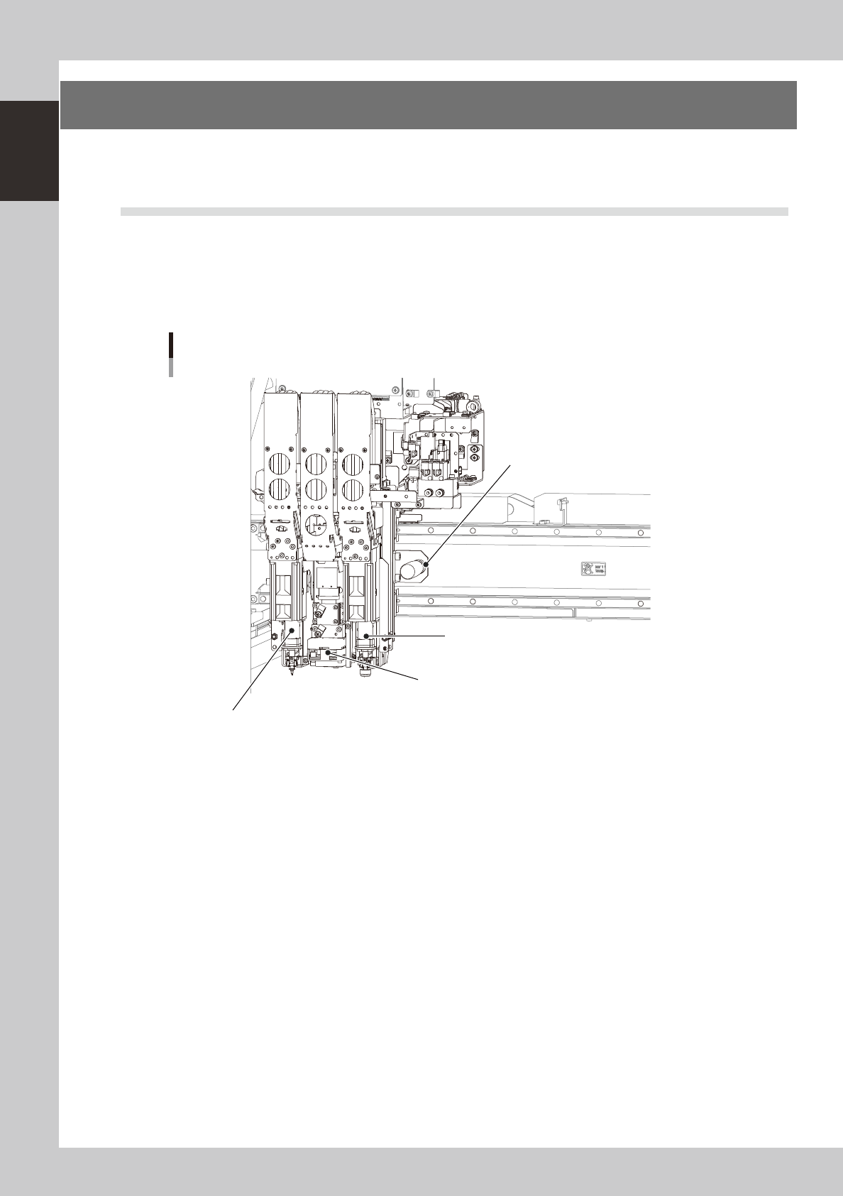
There are two types of head assemblies for the YC8: one is the V1 head unit (single head type) and the other is
the V2 head unit (dual head type). Both head units have a fiducial camera in the center.
The figure below shows the V2 head unit. The right-hand head is Head 1 and the left-hand head is Head 2 as
viewed from the front of the machine. The spacing of the nozzles attached to each head is 105mm. (The V1
head unit does not have Head 2.)
Head assembly
V2 head unit
Fiducial camera & lighting unit
Handle for moving head assembly
Head 1
Head 2
23105-N8-00
1-7
1
Part names and functions
3.2 Nozzle types
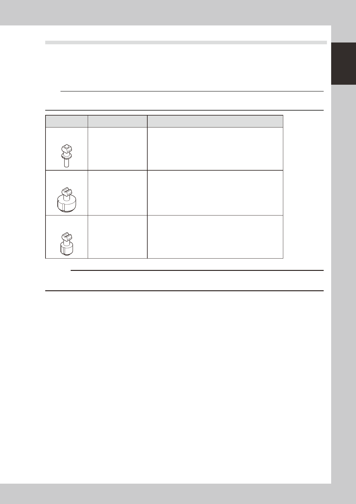
To ensure stable component pickup, the correct nozzle that matches the component must be used. The
following sections explain typical nozzles which can be attached to each head.
n
Standard nozzle and option nozzles
The standard nozzle for the YC8 is Type 63A and Type 65A.
n
NOTE
Type 64A nozzles can be selected as options. When an optional nozzle station is used, adapters are required to
accommodate Type 64A nozzles in the nozzle station.
Nozzle type Head No. Typical Components
Type 63A
(standard)
1, 2
4532 to 7343 size components, SOP 10mm to 20mm, 5mm to
16mm sq. QFP, etc.
Type 65A
(standard)
1, 2 16mm to 54mm sq. QFP and BGA, long connector, etc.
Type 64A
(option)
1, 2 SOP 30mm, 15mm to 30mm sq. QFP and BGA, etc.
c
machines.
1-8
1
Part names and functions
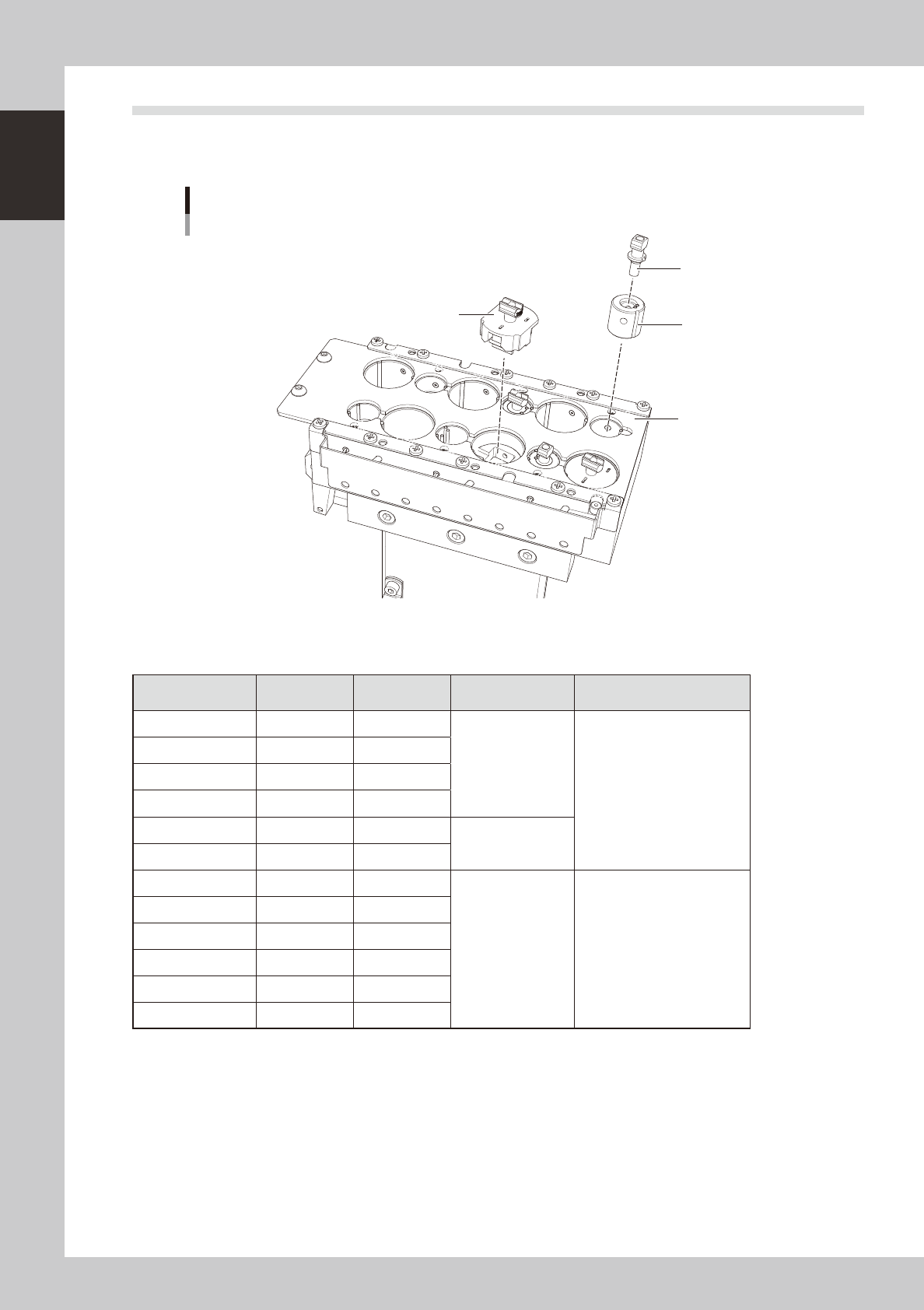
3.3 Nozzle station (option)
The nozzle station accommodates various nozzles for automatic change.
The drawings below show the nozzle station No. and the allotted head No. and mating nozzle type.
Nozzle station
Adapter
Machine rear side
Machine front side
Nozzle station No.
Option nozzle
(63A, 64A)
Custom nozzle
1
7
2
8
3
9
10
4
11
5
12
6
23106-N8-00
n
Nozzle station No. and allotted head
Nozzle station No.
V1 head unit
(single head)
V2 head unit
(dual head)
Nozzle Note
1 Head 1 Head 1
Custom nozzle
Type 63A and Type 64A
nozzles can also be
accommodated by using an
adapter.
2 Head 1 Head 1
3 Head 1 Head 2
4 Head 1 Head 1
5 Head 1 Head 1
Type 65A
6 Head 1 Head 2
7 Head 1 Head 1
Custom nozzle
8 Head 1 Head 1
9 Head 1 Head 2
10 Head 1 Head 1
11 Head 1 Head 1
12 Head 1 Head 2