YC8_Ope_E.pdf - 第76页
2-26 2 asic operation 4. Preparing the component supply unit 4.1 Setting the tape c Always use an external setup power station to set the tape. The tape cannot be set directly on the mounter. TIP For detailed i…
2-25
2
asic operation
4
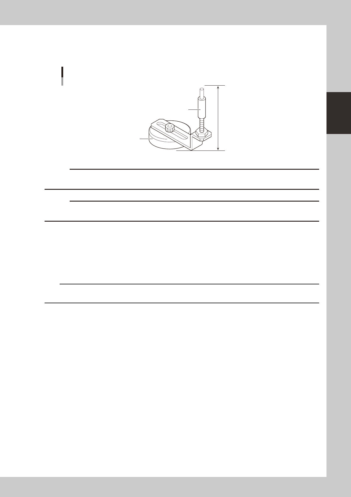
Place the push-up pins in the correct positions on the push-up plate.
Push-up pins are attached on the push-up plate by magnet. Considering the shape and size of the
board, place the push-up pins on the push-up plate so that they uniformly support the board, including
the edge of the board.
60mm
Push-up pin
Support pin
Magnet stand
23204-N8-00
c
height.
c
Set the push-up pins in positions where they will not interfere with the conveyor rails and other parts when the push-up
plate is raised.
5
Raise the push-up plate.
Check safety and press the [Push Up] button on the Setup screen. The push-up plate moves up to clamp
the board.
6
Check that the board is uniformly clamped on the conveyor.
Lightly tap on the board and also check for warping of the board from the side. If the board is
supported evenly with no warping, the adjustment is okay.
TIP
It may be convenient to mark the positions of the push-up pins on the plate (with a label, magic marker, etc.) for each
board type.
7
Remove the board from the conveyor.
Press the [Push Up] button on the Setup screen to lower the push-up plate and then remove the board.
2-26
2
asic operation
4. Preparing the component supply unit
4.1 Setting the tape
c
Always use an external setup power station to set the tape. The tape cannot be set directly on the mounter.
TIP
For detailed information on the external setup power station, refer to the separate "SS FEEDER User's Manual".
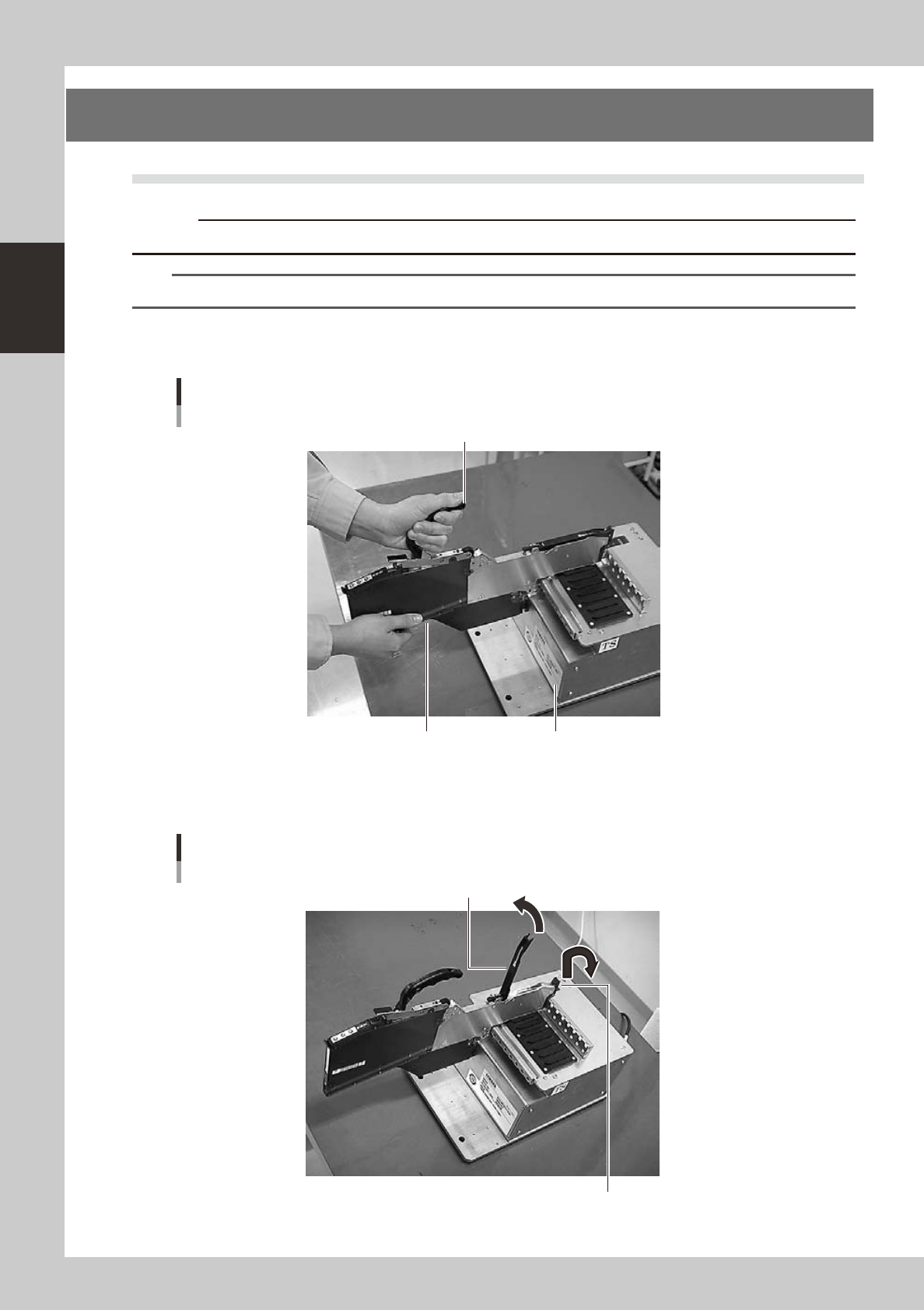
1
Set the feeder.
Place the feeder in the external setup power station.
Setting the feeder
Handle
Feeder External setup power station
23205-N8-00
2
Raise the tape guide assembly.
Lower the front lever for the tape guide while lifting it, and raise the tape guide assembly.
Raising the tape guide assembly
Tape guide assembly
Tape guide front lever
23206-N8-00
2-27
2
asic operation
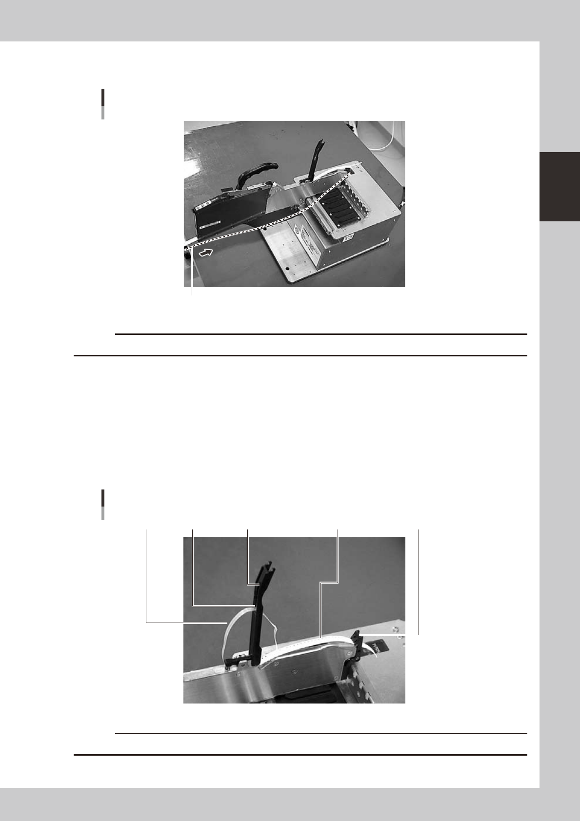
3
Set the tape in the tape feeder.
Insert in the hole on the rear of the feeder.
Mounting the tape
Tape
23207-N8-00
c
4
Peel off the top tape.
The tape consists of 2 layers. One is a "carrier tape" holding the electronic component and the other is a
"top tape" covering the upper surface of the component. Peel off the top tape.
5
Set the carrier tape.
Run the carrier tape through the hole in the tape guide front lever.
6
Set the top tape.
Run the top tape through the notch in the tape guide assembly. Be sure to pull out enough tape so the
top tape reaches the take-up roller.
Carrier tape and top tape
Top guide assemblyBottom plateTop tape Carrier tape Tape guide front lever
23208-N8-00
c