YC8_Ope_E.pdf - 第67页
2-17 2 asic operation 3. Star ting and stopping the machine This section explains routine procedures for starting and tur ning off the machine according to the flow charts below . Starting and turning off machine Produ…
2-16
2
asic operation
n
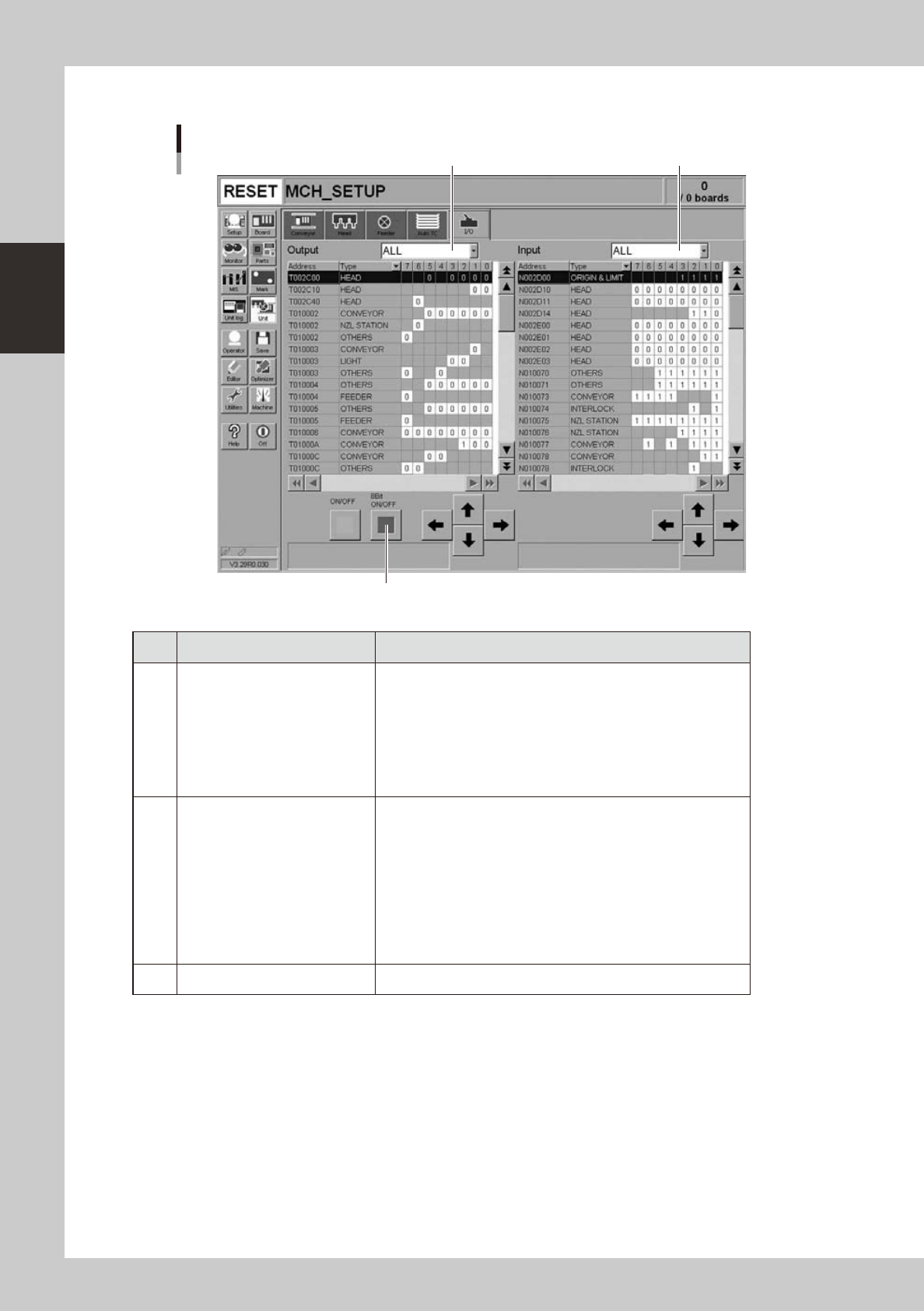
Manual I/O operation
[Unit] – [I/O] screen
1 2
3
24209-N8-00
Button name Function
1 Select output display group
Select the output group for display in the "Output" status list. The
following groups can be selected:
• ALL
• NSTA (nozzle station)
• LIGHT
• CONV (conveyor)
• HEAD
• OTHERS
2 Select input display group
Select the input group for display in the "Input" status list. The
following groups can be selected:
• INTLCK (interlock)
• SRV (servo origin limit)
• FDR (feeder)
• NSTA (nozzle station)
• CONV (conveyor)
• LIGHT
• HEAD
• OTHERS
3 ON/OFF Turns the selected valve on or off.
2-17
2
asic operation
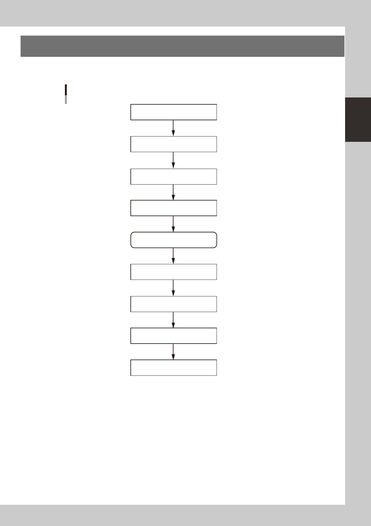
3. Starting and stopping the machine
This section explains routine procedures for starting and turning off the machine according to the flow charts
below.
Starting and turning off machine
Production (Running)
Press emergency stop button
Return axes to origins
Turn off power switch
Check before operation
Preform return-to-origin
Specify operator
Press [Off] button on screen
Program is loaded.
Return-to-origin dialog box appears.
Move-to-origin dialog box appears.
Shut down dialog box appears.
Finish board production.
Setup screen appears.
Turn on power switch
23201-N8-00
2-18
2
asic operation
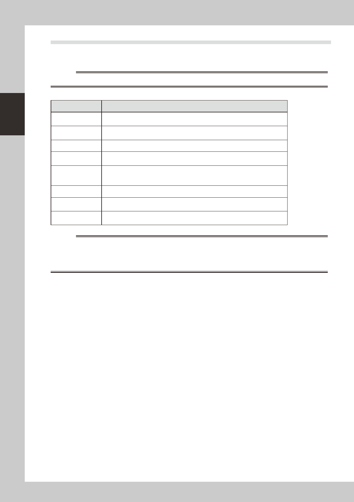
3.1 Pre-operation check
e
Check the following points before turning on the power.
w
WARNING
n
Pre-operation checklist
Check item Checkpoint
Air
Check that the upper display on the air pressure gauge, which is at the front lower left of
the machine, shows 0.40 MPa.
Power supply
Check that the specified power is connected to the power supply box located behind the
front lower right panel of the machine.
Safety cover Check that the covers are closed.
Feeder Check that feeders are securely attached to the feeder plate and are not tilted.
Check that no chips or debris adhere to the feeders.
Conveyor Check that no chips or debris are on the conveyor.
Check that the conveyor units do not interfere with each other, such as push-up pins
under the conveyor rails.
Head Check that each nozzle is correctly installed to the head.
Nozzle
Check that the nozzle tips are not nicked, solder does not adhere to the nozzle tips, and
nozzle spring-action is smooth.
ATS15 (option)
Check that no pallet is on the pallet stage, the door is closed, and the door switch is set
to "CLOSE".
w
WARNING