YC8_Ope_E.pdf - 第44页
1-9 1 Part names and functions 4. Component supply section The feeder setup section is equipped with feeder plates for installing feeders such as tape feeders, and power supply connectors and air connectors for driving o…
1-8
1
Part names and functions
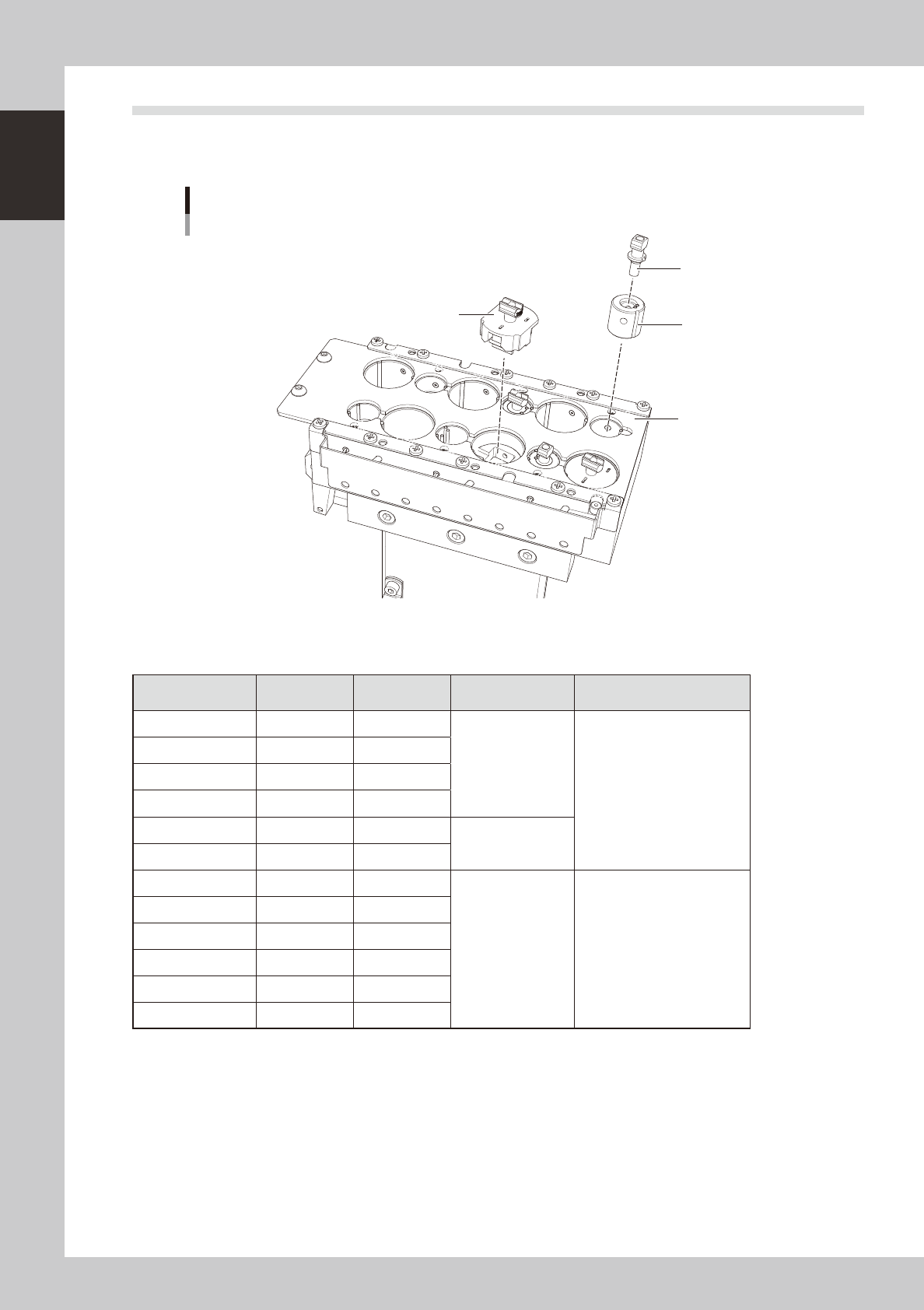
3.3 Nozzle station (option)
The nozzle station accommodates various nozzles for automatic change.
The drawings below show the nozzle station No. and the allotted head No. and mating nozzle type.
Nozzle station
Adapter
Machine rear side
Machine front side
Nozzle station No.
Option nozzle
(63A, 64A)
Custom nozzle
1
7
2
8
3
9
10
4
11
5
12
6
23106-N8-00
n
Nozzle station No. and allotted head
Nozzle station No.
V1 head unit
(single head)
V2 head unit
(dual head)
Nozzle Note
1 Head 1 Head 1
Custom nozzle
Type 63A and Type 64A
nozzles can also be
accommodated by using an
adapter.
2 Head 1 Head 1
3 Head 1 Head 2
4 Head 1 Head 1
5 Head 1 Head 1
Type 65A
6 Head 1 Head 2
7 Head 1 Head 1
Custom nozzle
8 Head 1 Head 1
9 Head 1 Head 2
10 Head 1 Head 1
11 Head 1 Head 1
12 Head 1 Head 2
1-9
1
Part names and functions
4. Component supply section
The feeder setup section is equipped with feeder plates for installing feeders such as tape feeders, and
power supply connectors and air connectors for driving optional units. An auto tray changer (ATS15) can
also be installed on the rear of the YC8 as an option.
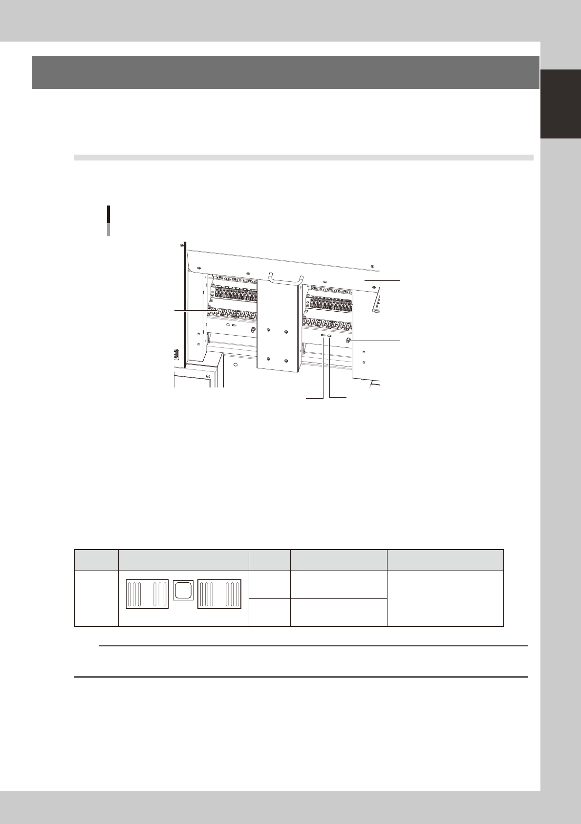
4.1 Supplying components from feeder plates
Tape feeders and stick feeders are installed on two 14-feeder plates, and operate by electric power supplied
from the mounter.
YC8 feeder setup section
Two fixed 14-feeder plates
Safety cover
Air connector
Power supply connector
Power supply connector (for dump station)
14-feeder plate
23107-N8-00
Power supply connector
When using optional units such as stick feeders, plug the power cord into these connectors. The connectors labeled
"DUMP" are only for dump stations.
Air connector
Use these air connectors when using an optional device such as an air blow gun. Connect the air tube (outer diameter
4mm) to supply compressed air to the optional device from the mounter.
n
Head No. and feeder set No.
Some feeders cannot be reached by a head depending on the head assembly configuration and X-axis movement range.
The tables below show feeder set numbers that can be accessed by each head of the machine.
Type Layout Head No. Accessible feeder set No.
Number of feeders than can be
attached
Two fixed
14-feeder
plates
1
14
15
28
1 1 to 19
28 when 8mm feeders are used
2 8 to 28
n
NOTE
Accessible feeder positions may differ from the above when the Feeder Definition parameter in component
information is set to "Teach" or "Relative".
1-10
1
Part names and functions
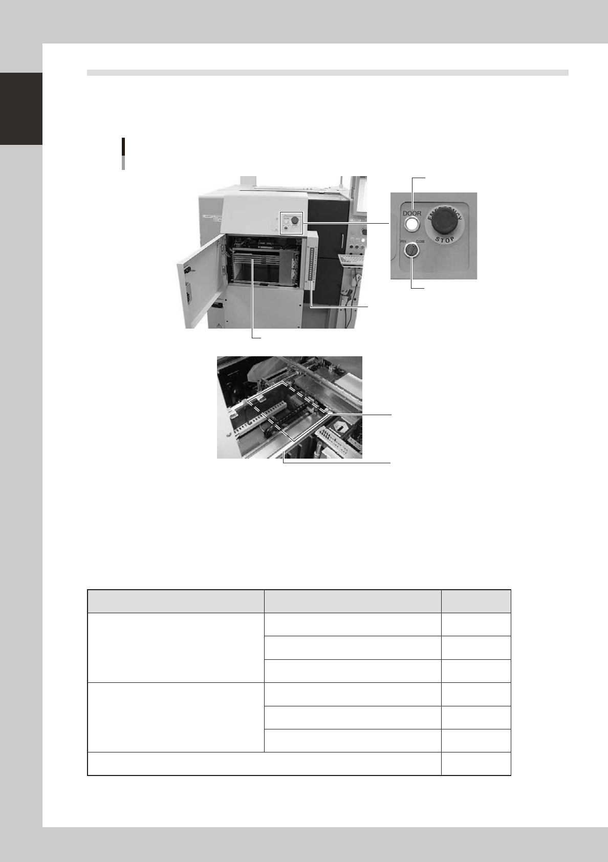
4.2 Supplying components from tray changer (ATS15)
Major part names and their functions of the tray changer (ATS15) are explained below.
4.2.1 ATS15 main unit
Tray changer main unit
ATS15
Pallet indicator
Guide rail
Pallet clamp position (work position)
Door switch
Door indicator
Pallet (Up to 15 pallets can be stored at 12.5mm pitch.)
23108-N8-00
Door switch
Setting this switch to "OPEN" unlocks the door and the DOOR indicator turns off.
Pallet indicator
The indicator lamps for the pallet No. set in the parts information are lit up. When the tray components on a pallet are
used up, the indicator lamp for that pallet No. flashes (see below). After setting new a pallet in the ATS15, press the
flashing indicator button to reset it.
n
Pallet indicator lighting pattern
Pallet condition Component condition Indicator status
One component type on one pallet
Components have been supplied. ON
Used up all components. Flashing
Components are currently being used. ON
Two or more components types on one pallet
All components on pallet have been supplied. ON
Used up all components. Flashing
Used up at least one type of component. Flashing
Components to be used are not specified in board data. OFF