YC8_Ope_E.pdf - 第50页
Chapter 2 Basic operation Contents 1 1.1 Canceling emergency stop 2- 1 1.2 Clearing an error 2- 2 1.3 Typical err ors and troubleshooting 2- 3 8 …
1-14
1
Part names and functions
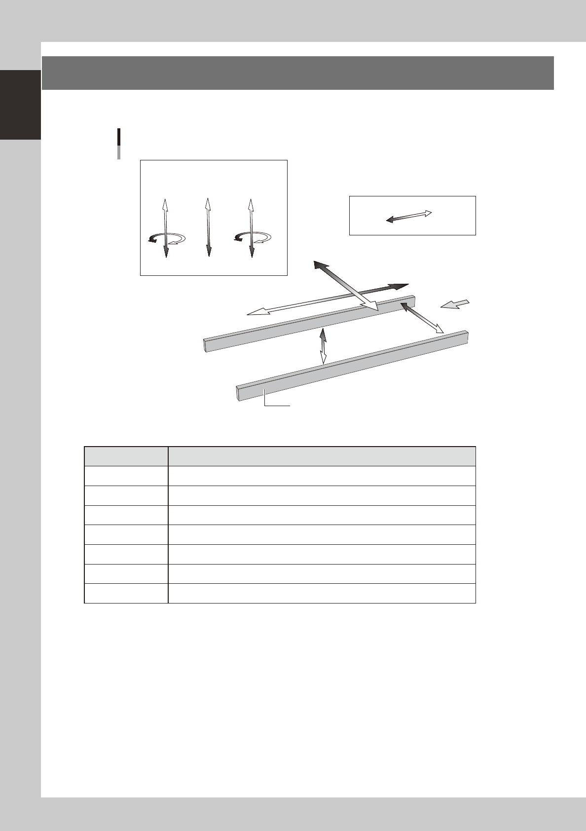
6. Axis configuration
The machine axis configuration and operation are shown in the drawing and table below.
Y axis
Z2 CZ Z1
X axis
W axis
PU axis
Plus direction
Minus direction
Board
Conveyor rail
R2 axis
R1 axis
Head
Axis configuration
23113-N8-00
n
Function of each axis
Axis Function
X Moves the head assembly in parallel with the board flow on the conveyor.
Y Moves the head assembly perpendicular to the board flow on the conveyor.
Z1, Z2 Moves the component pickup/mount head vertically.
R1, R2 Rotates the nozzle shafts of each head.
CZ Moves the fiducial camera unit vertically.
W Changes the conveyor width.
PU Moves the push-up plate vertically.

Chapter 2 Basic operation
Contents
1
1.1 Canceling emergency stop 2-1
1.2 Clearing an error 2-2
1.3 Typical errors and troubleshooting 2-3
8
8
2.2 Setup screen 2-11
2.3 Unit screen 2-12
3. Starting and stopping the machine 2-17
3.1 Pre-operation check 2-18
3.2 Starting the machine 2-19
3.3 Warming up the machine 2-21
3
3.4.1 Conveyor unit setup flow 2-24
4. Preparing the component supply unit 2-26
4.1 Setting the tape 2-26
4.2 Setting a tape feed pitch 2-31
4.2.1 Setting a pitch from the mounter 2-31
4.2.2 Setting a pitch from an external setup power station 2-33
4.3 Setting the tray components 2-35
4.3.1 Setting the component trays in the pallet 2-35
4.3.2 Setting a pallet in the ATS15 2-36
5. Settings on the mounter side 2-37
5.1 Setting the "Package" parameter. 2-37
1
2-1
2
asic operation
1. Before operation
The following explains how to cancel emergency stop and clear errors. Read before operating the machine.
n
Cautions during machine operation
• Do not turn off the compressed air during operation. The machine may malfunction, as pneumatic devices are not
correctly controlled.
• Before beginning maintenance work, always make sure that no air pressure remains in air cylinders.
n
Cautions during power outages
If a power outage (blackout) occurs during automatic machine operation, always turn the main power switch off to
prevent faulty operation or machine damage after power has been restored. Also remove the boards that remain in the
machine.
1.1 Canceling emergency stop
Follow these steps to cancel emergency stop.
1
Release the emergency stop button.
When the emergency stop button is pressed, turn it clockwise to release it.
2
Check safety.
Before continuing the procedure, check the surrounding area for safety.
3
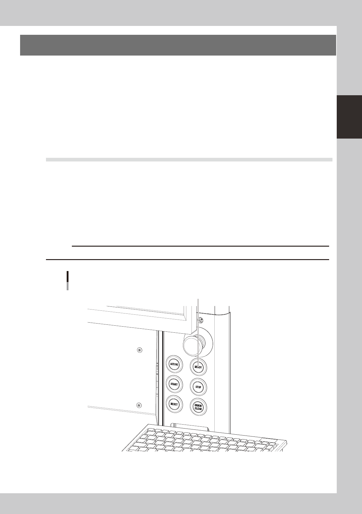
Press the [READY] button.
Pressing the [READY] button on the operation panel turns on the servomotors.
c
[READY] button
Press the [READY] button to turn on the servo.
23200-N8-00
4
Check the signal light and screen display.
Check that the red lamp of the signal light is off and the emergency stop sign on the top left (status
area) of the operation screen is now off.