00194716-04_AI_Abwurfbehaelter_Abfrage_X-D3_de_en.pdf - 第42页
Anhang Sensor Testmodus an der FCU 42 Option Verify Reject Bin Option Abfrage Abwurfbehälter LED an entspricht Abwurfbe hälter erkannt. ▪ LED 1 (H1) - Sensor S1 - Abfrage d er BE-Abwurfbehälter 6x6 des C&P20 bzw. CPP…
Anhang
Sensor Testmodus an der FCU
Option Verify Reject Bin Option Abfrage Abwurfbehälter 41
4 Anhang
4.1 Sensor Testmodus an der FCU
Für Maschinen mit der Sensoransteuerung über die FCU steht ein Testmodus an der FCU zur
Verfügung. Die Maschine muss hierzu eingeschaltet sein.
Je nach Maschinentyp ist eine andere FCU verbaut:
▪ SX4 bzw. X-Serie: X-FCU/X-Serie (ohne CAN-Knoten bzw. 1-Wire-Hub) [03059623-xx]
▪ SX1/SX2: B-FCU/B-Serie [03059666-xx]
Testmodus
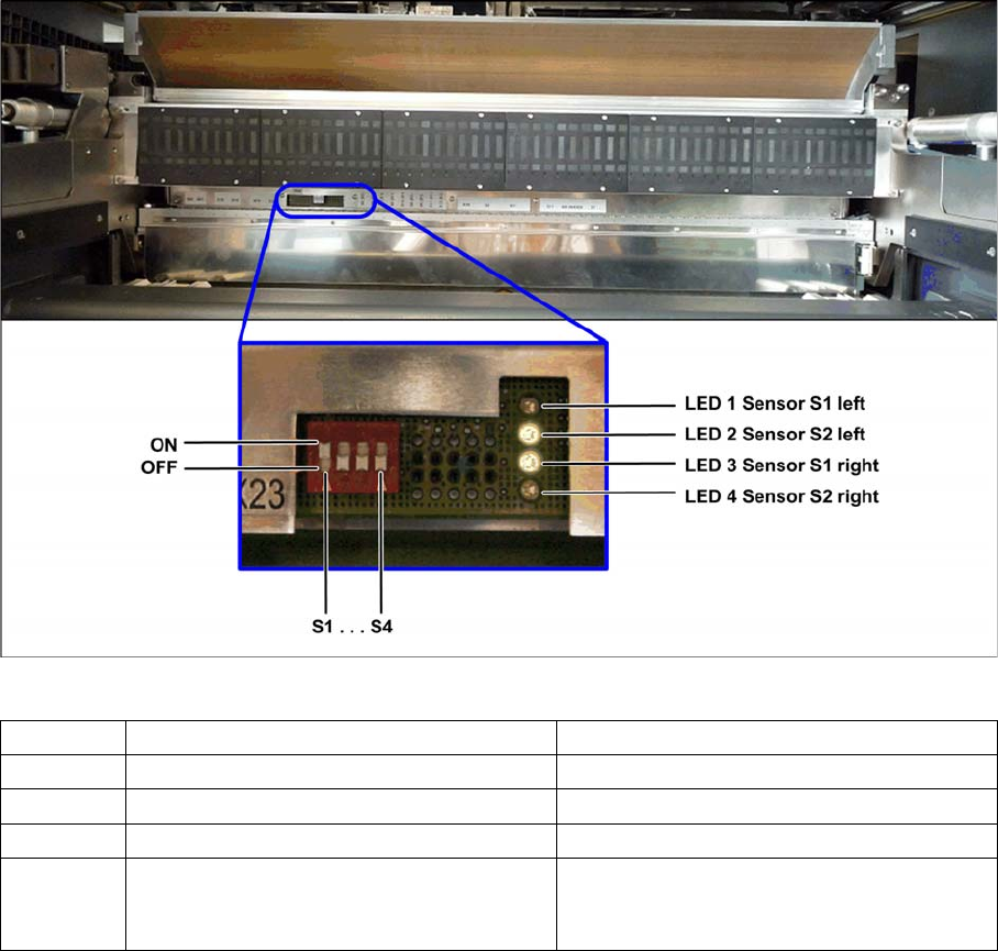
► Schalten Sie den Schalter S1 auf "OFF" um den Testmodus zu aktivieren.
Testmodus FCU - Beispiel: FCU für 60 Zuführmodule (SX1/SX2)
Anhand der LED-Anzeige rechts neben der Schalterreihe kann die Funktion der Sensoren für die
Abwurfbehälter überprüft werden.
Schalter ON (0) OFF (1)
S1 Testmodus ausgeschaltet Testmodus eingeschaltet
S2 FCU für 60 Zuführmodule (SX1/SX2) FCU für 40 Zuführmodule (X-Serie und SX4)
S3 Einzugsteuerung mit virtuellem Taster Einzugsteuerung ohne virtuellem Taster
S4 "HW Version 8" mit Ansteuerung von Gurt-
schneider, Abwurfsensoren und Pipetten-
wechslerfunktion
"HW Version 8" ohne Ansteuerung von Gurt-
schneider, Abwurfsensoren und Pipetten-
wechslerfunktion
Anhang
Sensor Testmodus an der FCU
42 Option Verify Reject Bin Option Abfrage Abwurfbehälter
LED an entspricht Abwurfbehälter erkannt.
▪ LED 1 (H1) - Sensor S1 - Abfrage der BE-Abwurfbehälter 6x6 des C&P20 bzw. CPP links
▪ LED 2 (H2) - Sensor S2 - Abfrage der Pipettenabwurfbehälter links
▪ LED 3 (H3) - Sensor S1 - Abfrage der BE-Abwurfbehälter 6x6 des C&P20 bzw. CPP rechts
▪ LED 4 (H4) - Sensor S2 - Abfrage der BE-Abwurf bzw. -Abfrage der BE-Abwurfbehälter TwinHead/
CPP mit stationärer Kamera rechts
► Schalten Sie nach Abschluss des Tests den Schalter S1 wieder auf "ON".

Introduction
Conventions for the Use of Safety Instructions Safety Instructions
Option Verify Reject Bin Option Abfrage Abwurfbehälter 43
1Introduction
This manual describes the installation of the "verify reject bin" in SIPLACE® X series and D3 machines.
1.1 Safety Instructions
1.1.1 Conventions for the Use of Safety Instructions
This manual contains notes that must be observed to guarantee your personal safety and to avoid dam-
age to equipment. These notes are highlighted by warning triangles and are indicated as follows accord-
ing to the level of risk:
DANGER
Nonobservance of these safety instructions may cause injury to personnel and damage to the
machine!
► Please observe the safety instructions in the user manual of the relevant machine for all
work!
DANGER
Definition
For the purposes of this manual, this indicates that fatal or severe injuries or considerable dam-
age to property will occur if this hazard warning is not observed.
WARNING
Definition
For the purposes of this manual, this indicates that fatal or severe injuries or considerable dam-
age to equipment may occur if these warning instructions are not followed.
CAUTION
Definition
For the purposes of this manual, this indicates that minor injuries or damage to property may
occur if this caution is not observed.
NOTICE
Definition
For the purposes of this manual, this note provides information about the product or indicates
a part of the manual that requires particular attention.