00194716-04_AI_Abwurfbehaelter_Abfrage_X-D3_de_en.pdf - 第77页
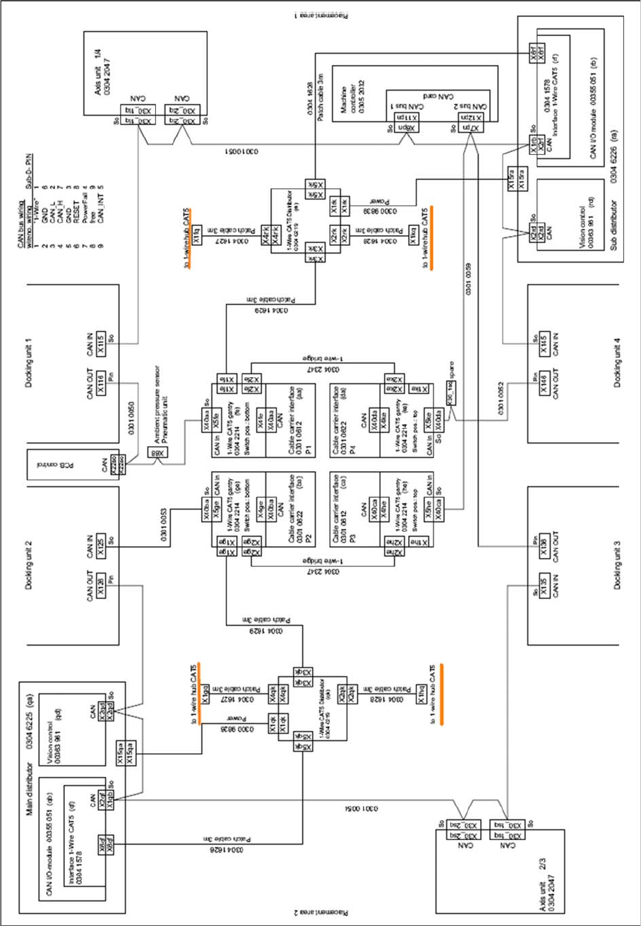
Installation Circuit Diagram for Sensors with 1 Wire Hub Module Final Work Option Verify Reject Bin Option Abfrage Abwurfbehälter 77 3.4 Final Work ► Use cable ties to fix all cables to suitable points. Make sure that no…
Installation
Fitting and Connecting the 1 Wire Hub Circuit Diagram for Sensors with 1 Wire Hub Module
76 Option Verify Reject Bin Option Abfrage Abwurfbehälter
1-Wire: wiring for X series verify reject bin option
Installation
Circuit Diagram for Sensors with 1 Wire Hub Module Final Work
Option Verify Reject Bin Option Abfrage Abwurfbehälter 77
3.4 Final Work
► Use cable ties to fix all cables to suitable points. Make sure that no cables or hoses can be damaged
or pinched.
► If you have disconnected the component trolley feed device, refit this. Please read the latest service
manual for the relevant machine prior to this.
► Refit the nozzle changer and reconnect it.
► Remove any assemblies which are not required and tools used from the machine. Check whether
the gantries and heads can move unobstructed in the machine and ensure that there is no risk of
collisions.
► Switch on the machine.
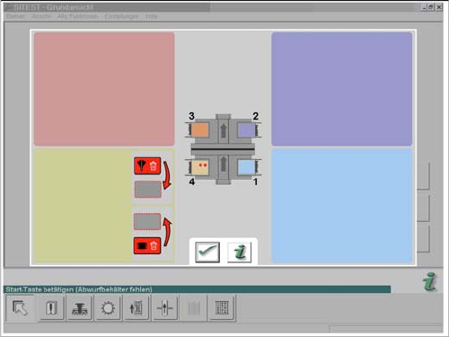
SW60x: message for verify reject bin option
► Check the settings with the help of the station soft-
ware. This shows the presence of the individual reject
bins. Use the user interface to make sure that all re-
ject bins are queried and shown correctly.
► If necessary, recheck the setting for the reject bin 6x6
sensor of the C&P20 or CPP head.
► Measure the nozzle changer and the pickup positions
of the changeover tables.
Installation
Final Work Circuit Diagram for Sensors with 1 Wire Hub Module
78 Option Verify Reject Bin Option Abfrage Abwurfbehälter