00194716-04_AI_Abwurfbehaelter_Abfrage_X-D3_de_en.pdf - 第68页
Installation Fitting the Sensors Fitting the Senso rs with C&P6/12 68 Option Verify Reject Bin Option Abfrage Abwurfbehälter Nozzle reject bin sensor for C&P6/12 (DLM) 1. Sensor 1 2. Sensor 2 Sensor S2 in p ark p…
Installation
Fitting the Sensors with C&P6/12 Fitting the Sensors
Option Verify Reject Bin Option Abfrage Abwurfbehälter 67
3.1.3 Fitting the Sensors with C&P6/12
Overview of sensors with C&P6/12 (DLM3)
► Fix the sensor S2 to the sensor carrier [03021179-xx] with the 2 plastic screws DIN85-M3x6-PA
[00305381-xx].
► Fix the fixture bracket (with the sensor on it) to the component reject bin carrier (2 screws DIN912-
M3x6).
► If a nozzle changer is fitted, fit sensor S2 for the nozzle reject bin. Use the 2 plastic screws DIN85-
M3x6-PA [00305381-xx] for this.
NOTICE
Screws
Only use the plastic screws provided!
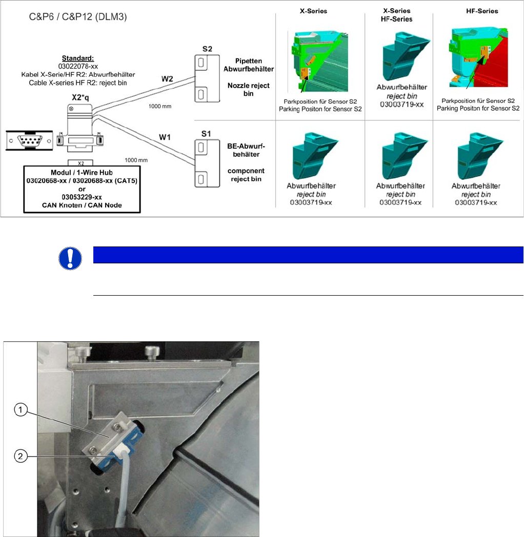
Sensor component reject C&P6/12 (DLM) on the X series
machines
1. Fixture bracket
2. Sensor S1
Installation
Fitting the Sensors Fitting the Sensors with C&P6/12
68 Option Verify Reject Bin Option Abfrage Abwurfbehälter
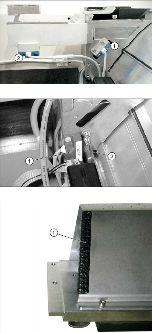
Nozzle reject bin sensor for C&P6/12 (DLM)
1. Sensor 1
2. Sensor 2
Sensor S2 in park position
► If there is no nozzle changer fitted, fit sensor S2 (1) in
the park position.
► Screw the sensor plate [03006260-xx] (2) provided
into place, next to the sensor.
► If there is a second nozzle changer row fitted in the
placement area with the C&P6 or C&P12 placement
head, we recommend insulating the edge of the pro-
tective sheet with a suitable edge protector (1) or ad-
hesive tape. Thus any damage of the reject bin
sensor cabels can be avoided.
Installation
Overview of sensor park position Connecting the Sensors to the CAN Nodes
Option Verify Reject Bin Option Abfrage Abwurfbehälter 69
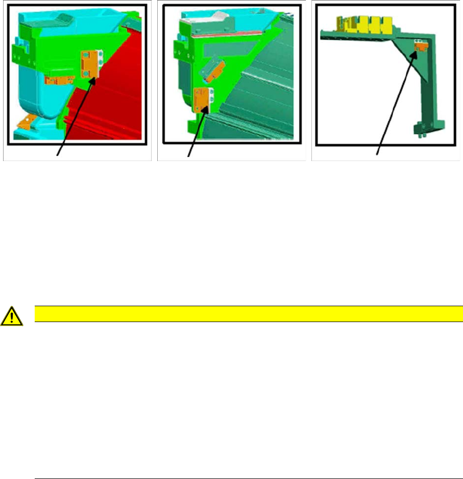
3.1.4 Overview of sensor park position
► Sensors which are not used must be fixed into the park position.
3.2 Connecting the Sensors to the CAN Nodes
The main task of the CAN node is to control the tape cutter.
The cabels (2) to (5) (see section "3.2.1 Circuit Diagram for Sensors with CAN Nodes" [ ➙ 71]) are run
as a default in the component feed device and connected to the CAN node option. The connectors can
therefore be found on the back of the component feed device, above the empty tape duct.
► Connect the X series/HF R2 cable for the reject bin [03022078-xx] to the cable from the CAN nodes
option [03035229-xx].
Sensor park position
for HF
Sensor park position
for X series reject bin
Sensor park position
for TwinHead with MTC
CAUTION
1-Wire-Hub or CAN node
Although some component feed devices already have the cables for the CAN node module
ready, the old version of the cutter control is still used. In this case, you either need to convert
to the CAN node module or use the 1 wire hub. Mixed configurations in the same machine are
not possible.
► Old cutter control board: [03006411-xx]
► New cutter control board for CAN node module [03052927-xx]
► From machine number B752 the component feed device has been converted fully to the
CAN node option.
► For conversion to the CAN nodes option, please contact your Siemens Service team.