00194716-04_AI_Abwurfbehaelter_Abfrage_X-D3_de_en.pdf - 第80页
Appendix Test Mode Sensor for FCU 80 Option Verify Reject Bin Option Abfrage Abwurfbehälter LED on means reject bin recognized. ▪ LED 1 (H1) sensor S1 verify com ponent reject bin 6x6 for C&P20 or CPP, left ▪ LED 2 (…
Appendix
Test Mode Sensor for FCU
Option Verify Reject Bin Option Abfrage Abwurfbehälter 79
4 Appendix
4.1 Test Mode Sensor for FCU
A test mode is available on the FCU for machines with the sensor control above the FCU. The machine
needs to be switched on for this.
The FCU may differ depending on the machine type:
▪ SX4 or X series: X-FCU/X series (without CAN node or 1-Wire-Hub) [03059623-xx]
▪ SX1/SX2: B-FCU/B series [03059666-xx]
Test mode
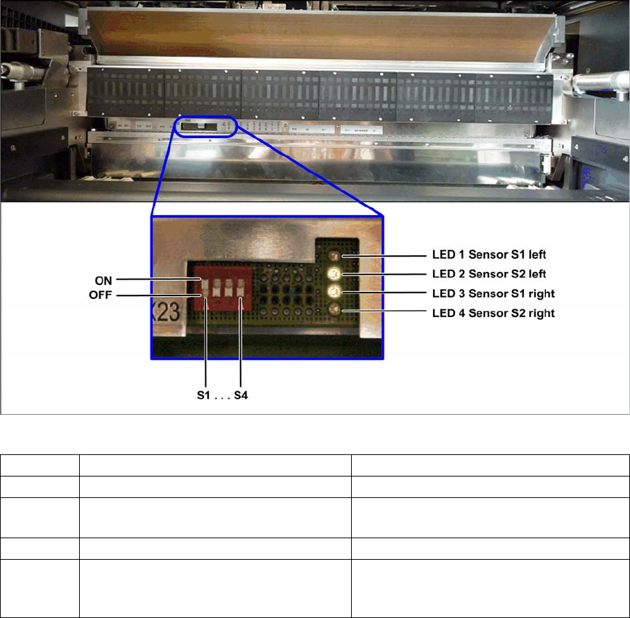
► To enable the test mode, set the switch S1 to "OFF".
Test mode FCU - Example: FCU for 60 feeder modules (SX1/SX2)
The LED display on the right, next to the row of switches, is used to check the functionality of the reject
bin sensors.
Switch ON (0) OFF (1)
S1 Test mode, switched off Test mode, switched on
S2 FCU for 60 feeder modules (SX1/SX2) FCU for 40 feeder modules (X series and
SX4)
S3 Feed control with virtual button Feed control without virtual button
S4 "HW version 8" with control system for tape
cutter, reject sensor and nozzle changer
function
"HW version 8" without control system for
tape cutter, reject sensor and nozzle chang-
er function
Appendix
Test Mode Sensor for FCU
80 Option Verify Reject Bin Option Abfrage Abwurfbehälter
LED on means reject bin recognized.
▪ LED 1 (H1) sensor S1 verify component reject bin 6x6 for C&P20 or CPP, left
▪ LED 2 (H2) sensor S2 verify nozzle reject bin, left
▪ LED 3 (H3) Sensor S1 verify component reject bin 6x6 for C&P20 or CPP, right
▪ LED 4 (H4) sensor S2 verify the component reject or verify the component reject bin TwinHead/CPP
with stationary camera, right
► After completion of the test, set switch S1 to "ON".
Backpage