0900766b8171bf63.pdf - 第12页
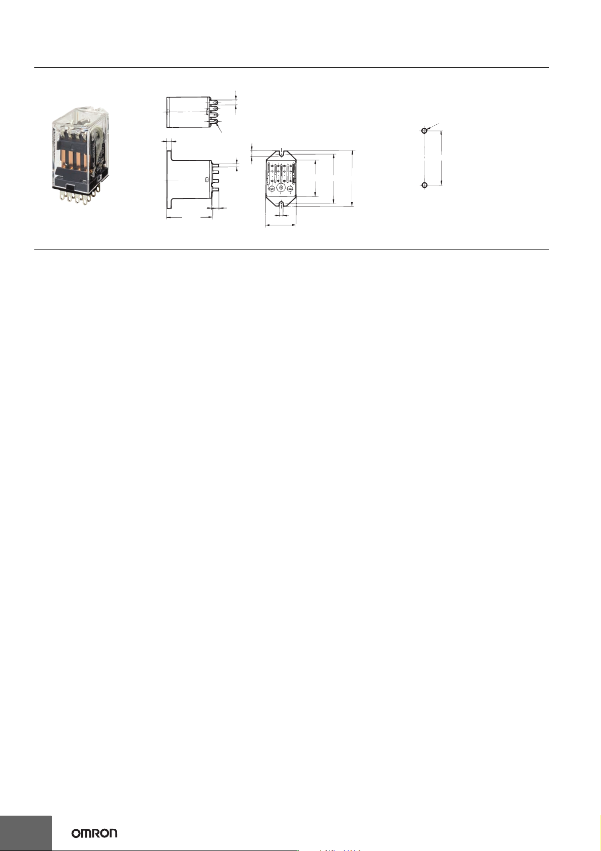
12 MY(S) Dimensions (Unit: mm) Fourteen, 1.2-dia. × 2.2 oval holes 2.6 2 0.5 0.5 6.4 36 max. 4.35 3.5 29 max. 38 44 max. 22.5 max. T wo, 3.5-dia. holes or M3 screw holes 38 ±0.2 Flange mount ing MY @ F Mounting Hole Dime…
MY(S)
11
Flange-mounting Relays: MY@F
Specifications
Contact Ratings
* With no icing or condensation.
Characteristics
Note: These are initial values.
*1. Measurement conditions: 1 A at 5 VDC using the voltage drop method
*2. Measurement conditions: With rated operating power applied. Ambient temperature condition: 23° C
*3. Measurement conditions: For 500 VDC applied to the same location as for dielectric strength measurement.
*4. Ambient temperature condition: 23° C
*5. This value was measured at a switching frequency of 120 operations per minute.
Contact form DPDT 4PDT, 4PDT (Bifurcated)
Load
Item
Resistive load
Inductive load
(cos φ = 0.4, L/R = 7 ms)
Resistive load
Inductive load
(cos φ = 0.4, L/R = 7 ms)
Rated load
5 A at 220 VAC
5 A at 24 VDC
2 A at 220 VAC
2 A at 24 VDC
3 A at 220 VAC
3 A at 24 VDC
0.8 A at 220 VAC
1.5 A at 24 VDC
Rated carry current
5 A 3 A
Maximum contact voltage
250 VAC, 125 VDC
Maximum contact current
5 A 3 A
Contact form
DPDT 4PDT, 4PDT (Bifurcated)
Contact materials
Ag Au plating + Ag
Type
Item
MY@F
Ambient operating temperature
*
−55 to 70° C
Ambient operating humidity 5% to 85%
Item Contact form DPDT 4PDT, 4PDT (Bifurcated)
Contact resistance
*1
50 mΩ max.
Operation time
*2
20 ms max.
Release time
*2
20 ms max.
Maximum
operating
frequency
Mechanical 18,000 operations/h
Rated load 1,800 operations/h
Insulation resistance
*3
100 MΩ min.
Dielectric
strength
Between coil and contacts
2,000 VAC at 50/60 Hz for 1 min.
Between contacts of
different polarity
Between contacts of the
same polarity
1,000 VAC at 50/60 Hz for 1 min.
Vibration
resistance
Destruction
10 to 55 to 10 Hz, 0.5-mm single amplitude
(1.0-mm double amplitude)
Malfunction
10 to 55 to 10 Hz, 0.5-mm single amplitude
(1.0-mm double amplitude)
Shock
resistance
Destruction 1,000 m/s
2
Malfunction 200 m/s
2
Endurance
Mechanical
AC: 50,000,000 operations min.
DC: 100,000,000 operations min.
(switching frequency: 18,000 operations/h)
Electrical
*4
500,000 operations min.
(rated load, switching
frequency: 1,800 operations/h)
200,000 operations min.
(rated load, switching
frequency: 1,800 operations/h)
Item Contact form DPDT 4PDT, 4PDT (Bifurcated)
Failure rate P value
(reference value)
1 mA at 5 VDC 1 mA at 1 VDC
Weight Approx. 35 g
Refer to the standards certifications and compliance
section of your OMRON website for the latest
information on certified models.
12
MY(S)
Dimensions (Unit: mm)
Fourteen, 1.2-dia. × 2.2 oval holes
2.6
2
0.5
0.5
6.4
36 max.
4.35
3.5
29 max.
38
44 max.
22.5 max.
Two, 3.5-dia. holes
or M3 screw holes
38
±0.2
Flange mounting
MY@F
Mounting Hole Dimensions
The above figure is for the MY4F.
Note: Refer to the terminal arrangement and
internal connections diagrams for the
MY2(S), MY4(S) and MY4Z(S).
MY(S)
13
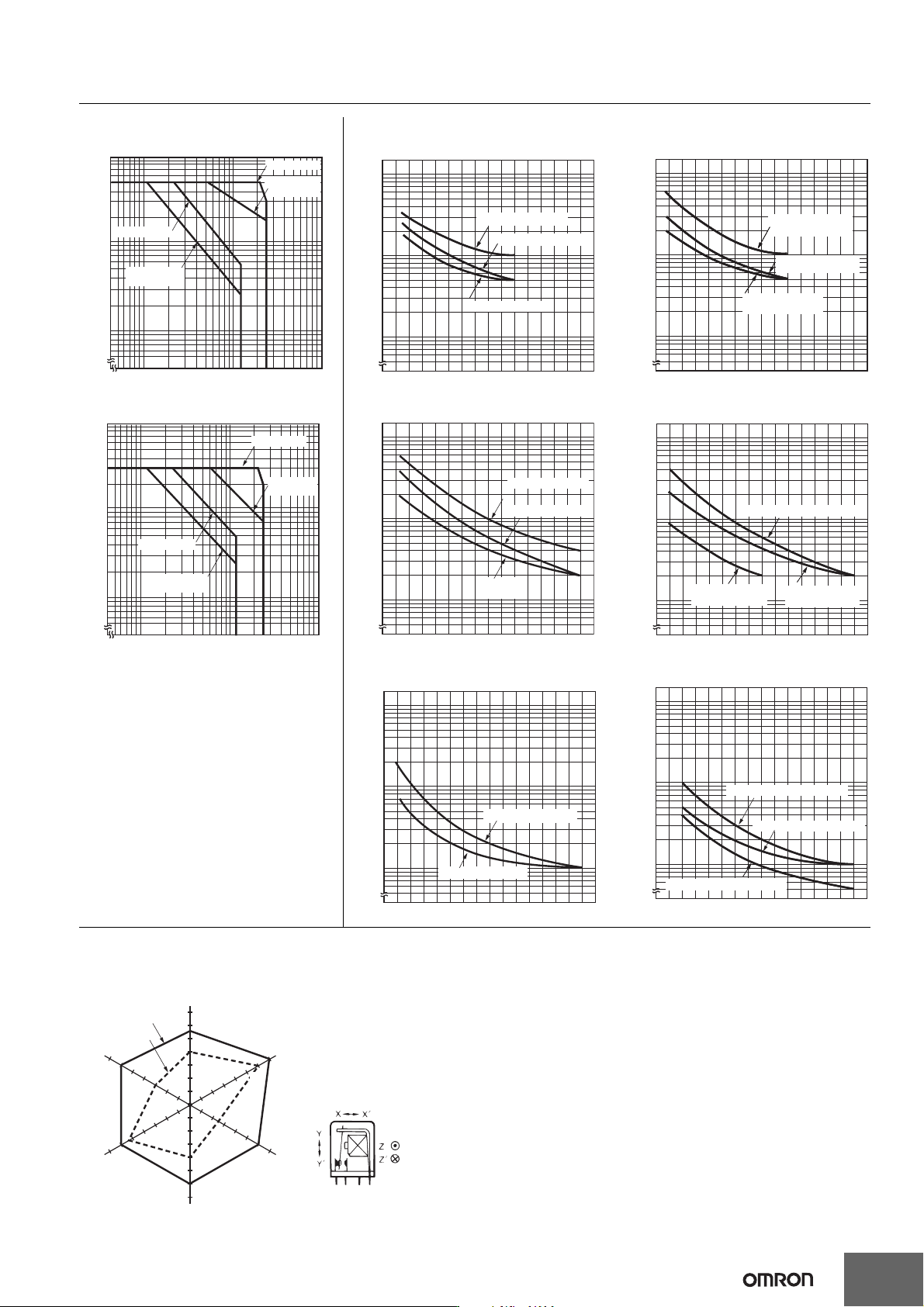
Engineering Data MY@F
Maximum Switching Capacity
MY2F
Endurance Curve
MY2F MY2F
MY4F and MY4ZF MY4F MY4F
MY4ZF MY4ZF
DC inductive load
(L/R = 7 ms)
DC resistive load
AC resistive load
AC inductive load
(cos φ = 0.4)
10
0.1
0.5
1
5
5 10 50 100 500
Contact voltage (V)
Contact current (A)
10
50
100
500
01234567
24 VDC resistive load
110 VAC resistive load
220 VAC resistive load
10
50
100
500
01234567
Contact current (A)
Number of operations (×10
4
operations)
10
50
100
500
01 2 3
10
50
100
500
01 2 3
24 VDC inductive load
(L/R = 7 ms)
110 VAC inductive load
(cos φ = 0.4)
10
50
100
500
01 2 3
Contact current (A)
Number of operations (×10
4
operations)
220 VAC inductive load
(cos φ = 0.4)
Contact current (A)
AC inductive load
(cos φ = 0.4)
10
0.1
0.5
1
5
5 10 50 100 500
Contact voltage (V)
DC inductive load
(L/R = 7 ms)
DC resistive load
AC resistive load
30 VDC
resistive load
110 VAC resistive load
220 VAC resistive load
10
50
100
500
012 3
Contact current (A)
Number of operations (×10
4
operations)
10
50
100
500
0 0.5 1.5
30 VDC inductive load
(L/R = 7 ms)
110 VAC inductive load (cos φ = 0.4)
220 VAC inductive load
(cos φ = 0.4)
10
50
100
500
0 1.0 1.5
Contact current (A)
Number of operations (×10
4
operations)
24 VDC resistive load
220 VAC resistive load
10
50
100
500
01 2 3
Contact current (A)
Number of operations (×10
4
operations)
24 VDC inductive load (L/R = 7 ms)
10
50
100
500
0 0.5 1.5
110 VAC inductive load (cos φ = 0.4)
220 VAC inductive load (cos φ = 0.4)
10
50
100
500
0 0.5
1.0
1.5
Contact current (A)
Number of operations (×10
4
operations)
Energized
Y
X
Z
X'
Z'
Y'
550
400
600
300
550
600
400
600
600
250
600
700
Unit: m/s
2
Not energized
Common Specifications for MY@F
Malfunctioning Shock
N = 20
Measurement: Shock was applied 3 times each in 6 directions along 3 axes with
the Relay energized and not energized to check the shock values that cause the
Relay to malfunction.
Criteria: Non-energized: 200 m/s
2
,
Energized: 200 m/s
2
Shock direction